A manufacturing plant does not care about theoretical bandwidth; it cares about downtime, throughput, and predictable maintenance windows. This field-oriented case study shows how an operator planned an 800G deployment across a leaf-spine backbone, selected optics that matched port and fiber constraints, and validated signal health before cutting over. It is written for network engineers, data center infrastructure teams, and field technicians who must make the change with measurable results and clear rollback options.
Why 800G deployment was risky in this factory network
In the reference scenario, the plant ran a 3-tier design supporting MES, SCADA historian ingestion, and vision systems. The existing core used 400G uplinks with mixed vendor optics, and the fiber plant was installed over multiple expansions. During an upgrade cycle, the team needed more east-west capacity to stop queue buildup during shift changes without extending the maintenance window beyond 4 hours.
The risk was not only “will it link up,” but also “will it stay up” under real conditions: patch-panel re-termination, vibration near machining bays, and temperature swings in equipment rooms. For engineers planning 800G deployment, the practical gating items were reach class, optical power budget margins, connector cleanliness, and switch transceiver compatibility. For the Ethernet side, they aligned link expectations with IEEE Ethernet behavior and optical module signaling requirements under the IEEE 802.3 family. IEEE 802.3 Ethernet Standard
Case study: manufacturing cutover plan for 800G deployment
The team executed the change like a production rollout rather than a lab demo. They planned optics and cabling as two parallel workstreams, then performed a staged activation with per-link monitoring. Before touching live traffic, they validated the fiber plant and optics inventory against the switch port map and the intended reach class, using measured link budgets rather than assumptions.
Network layout and what changed
They replaced selected spine uplinks from 400G to 800G while keeping the access layer stable. Concretely, the plant had 48-port ToR switches at each production zone and a spine pair aggregating to the core. The upgrade targeted 12 uplinks per spine per phase, totaling 24 high-speed links for the first cutover.
Optics and fiber choice used in the rollout
The team used a short-reach premise inside the main equipment rooms, but they had longer runs from one mechanical wing to the central patch closet. For those longer runs, they selected optics based on the facility’s measured end-to-end loss rather than “nominal reach.” They also standardized on a single transceiver family to reduce vendor-to-vendor variability in DOM telemetry and optics behavior.

Technical specifications snapshot (what they had to match)
Below is the practical spec checklist they used to decide between common 800G short-reach and longer-reach optical options. Note that exact module naming varies by vendor, but the key parameters are wavelength band, reach class, form factor, and operating temperature.
| Parameter | Typical 800G short-reach option | Typical 800G longer-reach option | Why it matters for deployment |
|---|---|---|---|
| Data rate | 800G (e.g., 8x100G lanes) | 800G (same lane concept) | Must match switch port capability and lane mapping |
| Wavelength / band | Short-reach multi-lane configuration (vendor-specific) | Longer-reach multi-lane configuration (vendor-specific) | Determines reach and dispersion sensitivity |
| Reach class | Designed for intra-room / short links (tens to a few hundred meters depending on loss) | Designed for longer runs (higher budget or different optics) | Must align with measured fiber loss, not marketing distance |
| Connector type | Commonly LC (duplex) or MPO/MTP (array), depending on module | Same physical connector family as module spec | Connector mismatch causes immediate install failures |
| Operating temperature | Typically wide for data center use (check datasheet) | Same requirement; ensure it exceeds site max ambient | Factory rooms can exceed typical “office” ranges |
| DOM / telemetry | Should expose temperature, bias, power, alarms | Same | Required for monitoring during and after cutover |
For module selection, the team referenced vendor datasheets for concrete parameters such as center wavelength, transmit/receive optical power, receiver sensitivity, and supported operating temperature. They also ensured the switch vendor’s transceiver compatibility list covered the exact module part numbers they purchased (for example, Cisco SFP-10G-SR is not relevant to 800G, but the same compatibility discipline applies). For 800G optics, you will typically see QSFP-DD or OSFP form factors; always confirm the exact switch port type before ordering.
In their documentation pack, they captured the module part numbers used in the first phase. In one common pattern, plants used third-party optics such as Finisar-branded or FS.com-branded 800G SR variants for short reach, but the decisive factor was whether the module passed the switch vendor’s qualification and delivered stable DOM readings under load. Example third-party 10G optics exist (such as FTLX8571D3BCL for 10G SR), but for 800G you must use the corresponding 800G-rated datasheet and ensure it is the correct form factor and electrical interface.
Fiber validation: how they avoided “it links today, fails next week”
In manufacturing, fiber is often “good enough” until you add higher-speed optics with tighter power and dispersion margins. The team treated fiber validation as a gate, not a courtesy step. They inspected every patch path, then tested with an OTDR and a loss meter across the planned link segments.
Measured checks they required before insertion
- End-to-end insertion loss for each planned uplink, measured in dB with the same patch cords and jumpers that would be installed.
- Connector inspection under a microscope (scratches, contamination, polish quality). They cleaned every interface immediately before insertion, using lint-free swabs and proper cleaning tools.
- MPO/MTP polarity verification when applicable, including mapping for transmit/receive lanes. They used consistent labeling across both ends of each link.
- OTDR traces to locate unexpected events (macro-bends, bad splices). Any trace anomaly triggered re-termination or jumper replacement.
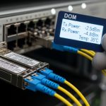
- DOM threshold expectations captured during a controlled link-up so alarms would be interpreted correctly during the maintenance window.
To frame the physical layer behavior, they also kept an eye on standardized optical performance expectations and test practices used in industry. While the Ethernet standard defines link behavior, the optical test procedures are typically grounded in widely adopted fiber measurement guidance and industry practice. Engineers commonly cross-check with fiber testing and connector handling guidance from reputable industry bodies. Fiber Optic Association

Selection criteria checklist for 800G deployment
When the team selected optics for the next phase of 800G deployment, they followed an ordered checklist that field engineers can reuse. This reduced rework and shortened the troubleshooting loop when something did not behave as expected.
- Distance and measured loss: Use OTDR and loss-meters on the actual installed path; compare to the module’s published power budget and receiver sensitivity.
- Switch compatibility: Confirm exact transceiver part numbers are supported for the specific switch model and port type (QSFP-DD vs OSFP, lane mapping, and expected DOM format).
- Connector and polarity: Verify LC vs MPO/MTP, and verify polarity/matrix mapping for multi-fiber array connectors.
- DOM support and monitoring: Ensure telemetry includes temperature and optical power plus alarm flags; validate sensor thresholds match your monitoring system.
- Operating temperature: Compare module operating range to the maximum ambient in the equipment room, including any proximity to heat-producing machines.
- Power and budget margins: Maintain conservative margins (not only “minimum works”) for aging, dust, and occasional patch-panel changes.
- Vendor lock-in risk: Decide whether you will use OEM-only optics or allow qualified third-party modules, and document the compatibility testing approach.
For cabling and optical testing practices, they also used structured storage and labeling conventions aligned with good operational hygiene. Storage and handling guidance is also commonly tied to best practices for data center infrastructure. SNIA
Pro Tip: During acceptance testing, capture DOM readings at three moments: immediately after insertion, after 10 to 15 minutes of steady link operation, and after a planned “stress window” that matches production traffic (for example, a sustained 60 to 80 percent utilization test). In several real cutovers, the optical power drift and temperature stabilization revealed marginal fiber cleanliness or a polarity mismatch that still allowed a basic link-up.
Common pitfalls and troubleshooting during 800G deployment
Even with a disciplined plan, 800G cutovers can fail in predictable ways. Below are concrete failure modes the team encountered, with root cause and the fix they applied.
Pitfall 1: “Link comes up, but errors spike within minutes”
Root cause: Connector contamination or a marginal optical receive power level due to higher-than-expected insertion loss. At 800G, small dB differences can drive high BER and frequent link resets.
Solution: Clean both ends again, verify connector polish, replace the shortest suspect jumper, and re-run optical power checks using DOM. If DOM shows low receive power or frequent alarm counters, treat it as a physical-layer issue, not a switch configuration issue.
Pitfall 2: “Intermittent drops only on one direction of traffic”
Root cause: MPO/MTP polarity or lane mapping reversed on one side. Some systems can partially link but will not support stable bidirectional traffic under load.
Solution: Verify transmit and receive mapping using the connector polarity scheme, then correct jumpers or flip the polarity adapter. Re-test with a controlled traffic pattern that generates sustained bidirectional flows.
Pitfall 3: “Works in the morning, fails after room temperature rises”
Root cause: Module temperature margin exceeded due to inadequate airflow or equipment-room thermal gradients. Some optics modules are rated for a wide range, but real installations can exceed the assumptions made during design.
Solution: Measure ambient temperature near the switch exhaust path, validate module operating range against datasheet, improve airflow, and confirm that the switch has correct fan profiles. Re-check DOM temperature sensors and alarm thresholds after the change.
Pitfall 4: “DOM telemetry looks wrong or monitoring shows no alarms”
Root cause: DOM implementation differences between OEM and third-party optics, or monitoring software expecting a specific sensor map.
Solution: Before cutover, validate telemetry fields in a staging environment or during a pilot link. Update monitoring templates and record expected sensor names, units, and alarm behaviors for each transceiver model.
Cost and ROI note for 800G deployment in a factory setting
Cost depends heavily on optics reach class, form factor, and whether you buy OEM-only modules. In many deployments, OEM 800G optics can cost several times more than qualified third-party modules per link, while the actual savings show up in reduced capital expenditure and faster replacement availability during failures.
For ROI, the plant’s business case was straightforward: downtime costs during shift changes and product throughput constraints. The team estimated that avoiding even a 1 to 2 hour outage per quarter could offset a meaningful portion of the optics and labor spend. They also accounted for TCO items: cleaning tools, connector inspection labor, extra spares, and the operational time required to validate DOM telemetry and fiber loss budgets.
Practically, they reduced risk by buying a limited number of spares for the exact module part numbers used in phase one, rather than generic “compatible” optics. That approach lowered mean time to repair (MTTR) when a field connector needed replacement after a patch-panel change.
FAQ: 800G deployment questions engineers ask on factory rollouts
What reach class should I choose for 800G deployment in a production facility?
Start with measured end-to-end loss on the actual path, then choose the module reach class that provides comfortable power-budget margin. If you only choose based on marketing distance, you may pass a basic link-up but fail under higher utilization or after cleaning variations.
Do I need to worry about connector polarity for 800G optics?
Yes, especially with MPO/MTP multi-fiber connectors where transmit and receive arrays can be reversed. Even if a link appears up, unstable bidirectional traffic under load can point to polarity or lane mapping issues.
How do I validate optics before the maintenance window?
Run a pilot activation on a non-critical pair of links, then collect DOM telemetry and error counters after the link stabilizes. Also perform fiber loss testing with the exact jumpers and patch cords you will use in production.
Are third-party 800G optics safe for uptime compared to OEM modules?
They can be safe if the modules are on the switch vendor’s compatibility list or have been validated in your environment. The biggest difference is operational: DOM telemetry mapping and alarm behavior may require monitoring template updates.
What is the fastest troubleshooting path when 800G links flap?
Check DOM alarms and optical receive power first, then inspect and clean connectors, then confirm polarity and lane mapping. Only after physical-layer indicators look healthy should you move to switch configuration or firmware considerations.
How should I plan spares and rollback for an 800G deployment?
Stock spares for the exact module part numbers and fiber jumpers used in phase one. Have a rollback path that reverts to the previous link rate and known-good optics if the pilot tests do not match production behavior.
If you want the next step, align your transceiver and cabling plan with your existing data center infrastructure practices using fiber optic transceiver and DOM telemetry monitoring. For a practical checklist on operational readiness, review network cutover planning before your next 800G deployment window.
Author bio: I have deployed and troubleshot high-speed optics in live environments, including staged cutovers where DOM telemetry and fiber loss margins determined success. I document field procedures so teams can execute 800G deployment with measurable uptime outcomes.