When a 400G upgrade stalls, it is usually not because the transceivers “do not work,” but because key features were overlooked: optics reach, electrical interface type, DOM telemetry, power draw, and thermal behavior. This buying guide helps data center and network engineers choose 400G modules that match switch ports and optical plant constraints. You will also get a practical head-to-head comparison of common 400G options and a checklist you can reuse during procurement reviews. Update date: 2026-05-04.
400G transceiver features that drive real link performance

In production, the most important features show up as link stability, margin, and operational consistency. For 400G Ethernet, the IEEE 802.3 family defines the physical layer behavior and lane grouping that determine what optics and cabling can pass compliance. In practice, you must align the module’s optical wavelength, reach, and modulation format with the fiber plant and the switch’s port profile. IEEE 802.3 Ethernet Standard
Reach and optical budget: features that decide “will it light up?”
For short-reach deployments, OM4 and OM5 multimode fiber are common because they reduce cost and simplify cabling. For longer runs, single-mode fiber with 1310 nm or 1550 nm optics becomes necessary. The transceiver’s specified reach is not just marketing distance; it is tied to receiver sensitivity, transmitter launch power, and link loss assumptions. When you check feasibility, verify fiber type, connector losses, patch panel loss, and worst-case aging.
Wavelength and lane mapping: features that prevent silent incompatibility
400G modules may use different internal lane counts and mapping strategies (for example, 8x50G, 16x25G, or coherent subcarriers depending on the interface). Even when the module “matches” on data rate, a mismatch in breakout expectations or port-side lane mapping can lead to link flaps. Always confirm the switch vendor’s transceiver compatibility list and the port mode (for example, native 400G vs breakout modes) before ordering.
DOM telemetry: features that reduce mean time to repair
Digital Optical Monitoring (DOM) features let you read temperature, bias current, received power, and sometimes alarms. With DOM, you can correlate early warning thresholds to field failures and plan proactive swaps. Many operators integrate DOM into telemetry systems for alerting and trend analysis; the practical value is faster isolation during outages.
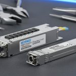
Head-to-head: 400G SR8 vs DR4 vs LR4 features for distance and cost
The fastest way to choose is to compare optic families by reach, fiber type, and typical power/thermal load. Below is a practical comparison of common 400G Ethernet optics. Real products vary by vendor and generation, so treat the values as representative ranges and confirm exact parameters on the datasheet of the specific part number.
| Option | Typical fiber type | Wavelength band | Nominal reach | Connector | Target interface | Operational temperature | Power feature (typ.) |
|---|---|---|---|---|---|---|---|
| 400G SR8 | OM4/OM5 multimode | 850 nm | ~70 m to ~100 m | LC (8-fiber MPO/LC breakout varies) | Direct detect, short reach | 0 to 70 C (commercial) or -5 to 85 C (extended) | ~6 to 12 W |
| 400G DR4 | Single-mode | 1310 nm | ~500 m to ~2 km | LC | Direct detect, intermediate reach | 0 to 70 C or -5 to 85 C | ~7 to 13 W |
| 400G LR4 | Single-mode | 1310 nm (often) | ~10 km | LC | Direct detect, longer reach | 0 to 70 C or -5 to 85 C | ~8 to 16 W |
For multimode SR8, the key features are fiber compatibility (OM4 vs OM5), connector handling (MPO polarity rules), and patch panel loss discipline. For DR4 and LR4, the key features shift toward dispersion tolerance, link budget, and connector cleanliness because single-mode optics are unforgiving about contamination. If you are running a mix of OEM and third-party optics, DOM support and diagnostic thresholds become essential for consistent operations.
When SR8 features win
SR8 features typically win when you are staying within the campus or within a data hall where multimode cabling already exists. In a leaf-spine fabric, SR8 can reduce cost and simplify upgrades because you avoid single-mode plant expansion. The tradeoff is stricter control over patch loss and MPO cleaning.
When DR4 or LR4 features win
DR4 and LR4 features win when you need to cross rows, meet longer aggregation distances, or connect to partner facilities. Single-mode optics add cost, but they reduce the need to rebuild cabling infrastructure. The tradeoff is operational discipline: you must follow connector cleaning standards and verify link budget with as-built measurements.
Pro Tip: In field audits, I have seen “it should work” links fail because patch cords and fanouts were swapped by contractors who did not preserve the original MPO polarity. Before you blame the transceiver, verify polarity end-to-end with a continuity check and then measure received power after the change.
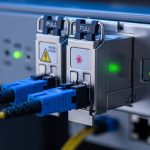
Compatibility features: switch port modes, DOM, and firmware expectations
Compatibility is where 400G projects most often slip schedule. The transceiver features you must validate are not just electrical data rate; they include port mode support, vendor-specific diagnostic behavior, and how the switch interprets DOM. Many switches also enforce optics constraints such as lane mapping and pre-emphasis settings. If these do not align, you may see link instability even when the module is “recognized.”
Port profile alignment: features that must match
Confirm whether the switch port expects a specific electrical interface (for example, QSFP-DD 400G SR8 vs a different 400G optics profile). Some platforms treat optics as “profiles” that drive internal equalization. If you use a transceiver that advertises a different profile, the switch may refuse to initialize or may initialize with reduced margin.
DOM and alarm thresholds: features that affect operations
DOM implementation varies across vendors. Some modules expose richer telemetry and provide alarm flags earlier in the failure curve; others are more limited. Operationally, you want DOM features that integrate cleanly with your monitoring stack and that produce stable alarm semantics. If your monitoring expects specific thresholds, third-party optics can create false positives or blind spots.
Power and thermal features: features that protect the slot
400G optics can draw enough power to stress airflow in dense chassis. A module that is within spec on a bench might exceed thermal headroom in a high-ambient rack. Check the switch’s transceiver power class and verify that your data hall meets the minimum airflow and inlet temperature targets. If you are doing retrofits, measure inlet temperature at the exact rack location, not a nearby aisle sensor.
Cost and ROI features: OEM vs third-party optics and the real TCO math
Cost is not just the purchase price; it is the total cost of ownership (TCO) across inventory, spares strategy, and downtime. OEM transceivers often cost more up front but can reduce support escalations and speed RMA workflows. Third-party optics may reduce capex, but you must budget for compatibility testing, increased spares, and more frequent field validation. In practice, the best ROI comes from matching features to your environment and reducing “unknown compatibility” risk.
Realistic price ranges engineers see
As a rough field reference, 400G SR8 modules often land in a lower price tier than DR4 and LR4, with OEM pricing typically higher than third-party by a meaningful margin. During demand spikes, pricing can swing quickly, so procurement teams should use rolling quotes and include lead time risk. For TCO, include the cost of labor for swaps, the probability of failure, and the downtime cost per hour for your NOC.
Power feature impact on operating cost
Even small power differences matter at scale. Suppose a 400G optic averages 10 W; across 200 ports, that is 2 kW of optical power. Over a year, that becomes a non-trivial energy and cooling load, especially in facilities where power usage effectiveness is tight. When you choose modules, compare power features and ensure the chassis thermal design can handle peak conditions.
400G network planning
Selection criteria checklist: features to verify before you buy
Use this ordered checklist during vendor qualification and before raising a purchase order. It focuses on the features that most directly affect link bring-up, stability, and operational maintainability.
- Distance and fiber type: Confirm OM4/OM5 vs single-mode, and validate measured end-to-end loss and connector attenuation.
- Optics reach and wavelength: Match SR8 vs DR4 vs LR4 features to the actual route length, including patch panels.
- Switch port compatibility: Use the switch vendor transceiver matrix and confirm port mode and lane mapping expectations.
- DOM support and telemetry behavior: Verify DOM presence, key alarms, and whether your monitoring system can interpret it.
- Operating temperature: Check commercial vs extended ranges and verify rack inlet temperature meets the module’s limits.
- Power and thermal headroom: Compare module power features and ensure airflow targets are met at the slot location.
- Connector handling requirements: Confirm MPO polarity rules, cleaning method expectations, and fanout compatibility.
- Vendor lock-in risk: Run a compatibility test plan and decide whether you need OEM-only for mission-critical links.
Pro Tip: Before installing new optics in a live fabric, I schedule a “telemetry-only” pre-check: read DOM values in a maintenance window and watch for abnormal laser bias or received power drift trends. Catching early anomalies beats diagnosing after a remote outage.
Common pitfalls: troubleshooting 400G feature mismatches
Below are practical failure modes I have seen during deployments. Each includes the root cause and a field-tested solution path.
Pitfall 1: Link comes up briefly then flaps
Root cause: Port profile or electrical compatibility mismatch (lane mapping or equalization settings differ from what the switch expects). Sometimes it is triggered by firmware changes that alter optics initialization behavior.
Solution: Verify the module part number against the switch vendor’s compatibility list for your exact software version. Re-seat the module, check DOM for alarm flags, and if needed, test with an OEM optic known-good to isolate whether the issue is module vs port.
Pitfall 2: “No light” after install despite correct reach
Root cause: Connector contamination or MPO polarity reversal. This is especially common when patch cords are reworked during cable management.
Solution: Clean connectors with the correct procedure, then re-check polarity end-to-end. After cleaning, measure received power and compare to the module’s expected range from the datasheet. If you have access to an OTDR/OLTS workflow, confirm the worst-case span loss.
Pitfall 3: Thermal throttling or repeated resets at high inlet temperature
Root cause: The module is operating near its thermal limit due to reduced airflow, blocked vents, or high ambient conditions. Some chassis fail to meet targets when airflow paths are obstructed by cable bundles.
Solution: Measure inlet temperature at the rack and confirm fan trays operate correctly. Improve airflow management, reduce cable congestion near the transceiver slots, and consider modules with lower power features if the switch supports multiple compatible options.
Pitfall 4: Monitoring shows alarms you cannot interpret
Root cause: DOM feature differences across vendors or unsupported alarm semantics in your telemetry tooling.
Solution: Update your monitoring rules to match the module’s DOM implementation. Validate with a staged test: induce a controlled condition where possible (for example, disconnect a fiber to confirm the alarm behavior) and confirm the NOC dashboard reflects the correct severity.
DOM telemetry
Decision matrix: which 400G transceiver features fit your environment
Use this matrix to decide quickly. It assumes you are choosing between a short-reach multimode option and longer-reach single-mode options, and you care about operational stability and compatibility.
| Reader type | Primary constraint | Best-fit feature emphasis | Likely option | Why |
|---|---|---|---|---|
| Data center ops team | Fast deployment, predictable behavior | DOM alarms stability, switch compatibility, thermal margins | SR8 (if within reach) | Lower complexity optics and simpler cabling; easier maintenance when DOM is consistent. |
| Network architect | Distance across rows or halls | Link budget, wavelength match, connector discipline | DR4 or LR4 | Single-mode features extend reach without rebuilding multimode infrastructure. |
| Procurement with budget pressure | Capex reduction without surprises | Compatibility testing, vendor support model, TCO | Third-party only after validation | Lower purchase price can win, but only if feature behavior matches your monitoring and switch expectations. |
| NOC lead | Reduce MTTR | DOM coverage, stable alarm thresholds, clear diagnostics | OEM or validated third-party | Better telemetry reduces time spent guessing during outages. |
Which option should you choose?
If your patching and measured loss fit within the nominal reach, choose SR8 features for the simplest operational profile and lower optics complexity. If you need intermediate or long distances, prioritize DR4/LR4 features with verified link budgets and strict connector cleanliness processes. If you are considering third-party optics, treat compatibility as a first-class requirement: validate DOM telemetry behavior, confirm port profile support, and run a short pilot before scaling.
Next step: build a one-page optics worksheet using the 400G network planning checklist, then attach the exact module part numbers and switch firmware versions you will deploy.
FAQ
What features matter most for 400G transceiver selection?
Focus on optics reach (SR8 vs DR4 vs LR4), wavelength and connector type, DOM telemetry support, and power/thermal features that match the chassis. Compatibility with your switch port mode and firmware version is equally important to avoid link flaps.
Can I mix OEM and third-party 400G transceivers in the same switch?
Often yes, but only after validating with your specific switch model and software release. The biggest risk is DOM alarm semantics and port profile initialization behavior, so run a staged test before full deployment.
Do DOM features affect performance or only monitoring?
DOM features are primarily for monitoring and diagnostics, not raw link performance. However, practical performance issues become easier to detect early when DOM provides reliable alarms and received power telemetry, which lowers downtime.
How do I confirm fiber compatibility beyond the datasheet reach number?
Use measured end-to-end loss including connectors, patch panels, and any fanout components. Also verify MPO polarity rules for multimode links and clean connectors before measuring received power.
What operating temperature features should I check for dense racks?
Confirm whether the module is rated for commercial or extended temperature and verify the switch inlet temperature at the rack location. Dense deployments can reduce airflow and push modules toward thermal limits even when the ambient room temperature looks acceptable.
Where can I find authoritative standards for 400G Ethernet behavior?
IEEE 802.3 defines Ethernet physical layer expectations and related optical interfaces. For additional industry context on interoperability, review vendor guidance and reputable standards bodies; start with the IEEE reference and your switch vendor’s compatibility notes. ITU
Author bio: I have deployed 10G to 400G Ethernet optics in real data center change windows, focusing on bring-up, DOM telemetry validation, and fiber plant troubleshooting. I document field notes the way I would for a commissioning handover, with measurable checks and failure-mode lessons.