Moving from 400G to 800G is not just a port-speed upgrade; it is a system-level reliability and integration project. This article helps data center architects, network reliability engineers, and field deployment teams plan optics, transceiver compatibility, and thermal headroom so the migration survives both burn-in and real traffic bursts. You will see concrete reach and power tradeoffs, DOM and switch compatibility checks, and troubleshooting patterns observed during production rollouts.
Why the 400G to 800G jump breaks plans: link budgets meet thermal budgets

At 400G to 800G, the physical layer often remains fiber-based, but the optics density, lane aggregation, and electrical interface stress change rapidly. Many vendors use different implementations for 400G (commonly 8x50G PAM4 lanes) versus 800G (commonly lane counts and FEC framing that increase aggregate symbol processing). Practically, that means higher per-port power dissipation and more sensitive thermal gradients across the switch front panel.
Reliability engineers typically track these migration risks using MTBF-style thinking and accelerated stress testing concepts: if transceiver die temperature rises by even 5 to 10 C under worst-case airflow, lifetime under Arrhenius-type models can drop materially. The failure mode taxonomy also changes: you may see more marginal solder joint failures, higher incidence of receiver sensitivity drift, or optics latch/connector wear when modules are repeatedly re-seated during troubleshooting.
For Ethernet physical layer requirements and evolution, align your expectations with the standardization path. Even when your switch vendor supports a given speed, the underlying electrical and optical performance assumptions should match the IEEE Ethernet ecosystem: IEEE 802.3 Ethernet Standard.
Optics selection for 400G to 800G: what actually changes
In most deployments, you will choose between short-reach multimode and long-reach single-mode optics, plus different form factors (QSFP-DD, OSFP, and vendor-specific 800G pluggables). The critical differences are wavelength, reach, optical power class, connector type, and whether the transceiver supports your switch’s expected FEC and digital diagnostics.
Engineers commonly start with reach and fiber plant assumptions: MMF OM4/OM5 versus SMF, and whether you have enough margin after patch panel loss, MPO polarity handling, and aging. Then they validate the optics power budget against the switch’s receiver sensitivity targets and any required margin for BER under temperature extremes.
Core spec comparison (typical 400G vs 800G optics classes)
The table below shows representative classes you will encounter when planning 400G to 800G migrations. Exact numbers vary by vendor and part revision; always use the specific datasheet values for the exact module and host interface.
| Parameter | Representative 400G SR (MMF) | Representative 800G SR (MMF) | Representative 800G LR (SMF) |
|---|---|---|---|
| Typical data rate | 400G (aggregate) | 800G (aggregate) | 800G (aggregate) |
| Wavelength | 850 nm class | 850 nm class | 1310 nm class |
| Reach (typical) | 100 m on OM4/OM5 class | 100 m on OM4/OM5 class | 2 km class |
| Connector | MPO/MTP (multifiber) | MPO/MTP (multifiber) | LC (duplex) or MPO variant |
| Typical TX power class | Low-to-moderate mW per lane | Higher aggregate optical budget | Higher per-channel budget |
| Operating temperature | 0 to 70 C class | 0 to 70 C class (often) | -5 to 70 C class (common) |
| DOM support | Yes (diagnostics) | Yes (diagnostics) | Yes (diagnostics) |
| Key risk | Patch loss and MPO polarity | Thermal and lane-level margin | Connector cleanliness and SMF dispersion |
Deployment scenario: a leaf-spine rollout with 400G to 800G in production
Consider a 3-tier data center leaf-spine fabric where each top-of-rack leaf switch has 48 downlink ports and 24 uplink ports. The site runs 400G east-west traffic between leaves and spines, using OM5 MMF with MPO trunks, and the architecture is migrating to 800G uplinks for spine aggregation. During a phased rollout, engineers schedule link bring-up in windows where ambient intake temperatures stay below 26 C, while measured module temperature during traffic peaks is targeted under 65 C.
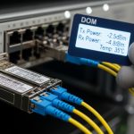
In practice, the team performs pre-checks before swapping optics: they verify patch panel loss using an OTDR or certified loss test, confirm MPO polarity mapping, and record DOM baselines (TX bias current, received optical power, and temperature) for each port. Only then do they replace 400G pluggables with 800G modules and run BER-focused verification plus traffic soak. In one common pattern, a single mis-terminated MPO polarity caused a subset of lanes to fail link training, even though the physical connector was fully seated.
Decision checklist: how reliability teams choose optics for 400G to 800G
Use this ordered checklist to reduce integration surprises and protect MTBF assumptions. It is designed for field teams who need repeatability across racks, not just a one-off lab success.
- Distance and fiber type: Confirm OM4 versus OM5 versus SMF, and verify the actual installed loss budget including patch panels and aging.
- Switch compatibility and lane mapping: Validate the transceiver is on the switch vendor compatibility list for the exact platform and software release.
- DOM telemetry expectations: Ensure the host reads the same diagnostic pages your tooling relies on (temperature, bias, received power). Mismatched DOM behavior can hide marginal conditions.
- Thermal headroom: Compare per-module power dissipation and check airflow constraints at the exact port row. Plan for worst-case blocked vents and fan speed reductions.
- Operating temperature range: If the site experiences > 30 C intake or hot-aisle recirculation, prioritize modules with appropriate temperature specifications.
- Connector and cleanliness process: MPO/MTP and LC cleaning SOPs must be enforced; optics class does not compensate for dirty ferrules.
- FEC and BER verification method: Align your test procedure with Ethernet link bring-up and BER monitoring capabilities; verify error counters under load.
- Vendor lock-in and supply risk: OEM optics may have lower integration variance, but third-party options can succeed if vendor validation is documented and returns are tracked.
For fiber performance guidance and installation best practices, teams often cross-check with structured fiber testing guidance from industry groups such as the Fiber Optic Association: Fiber Optic Association.
Pro Tip: In 400G to 800G migrations, the most expensive failures are not “no light” events; they are lane-level marginal links that pass initial training but degrade under thermal cycling. Capture DOM baselines at bring-up and again after a traffic soak that matches your worst-case ambient airflow, then set alert thresholds on received power drift rather than only link up/down state.
Common mistakes and troubleshooting patterns in 400G to 800G
Below are concrete failure modes seen during real deployments, with root causes and fixes you can apply immediately.
Link flaps after initial success
Root cause: Thermal margin is insufficient or airflow is uneven across the port row, causing receiver sensitivity to drift and trigger retraining. This is common when modules run hotter than expected due to adjacent high-load ports or partially blocked intake.
Solution: Measure module temperature via DOM and compare against the datasheet operating range. Rebalance port utilization, adjust fan profiles, and validate airflow with smoke testing or differential pressure checks.
Partial lane failure after MPO re-cabling
Root cause: MPO polarity mismatch or incorrect fiber mapping in patch panels. With higher lane counts and stricter lane alignment, a polarity error can show as “sometimes up” behavior depending on which lanes are sampled during training.
Solution: Perform end-to-end polarity verification using a certified tester and label patch panels. Re-terminate or re-map fibers until the received optical power per lane group is within expected range.
“Works in lab, fails in rack” due to power budget mismatch
Root cause: In the field, additional patch points and connector contamination add loss. The optics class may still meet nominal reach, but your BER under load can fail because you lost too much margin.
Solution: Re-run loss testing on the installed fiber path and clean connectors using validated procedures. If budget is tight, switch to a higher-power optics class or reduce the number of patch transitions.
DOM telemetry gaps break monitoring and delay root cause
Root cause: Third-party optics that implement DOM differently can cause missing or mis-scaled telemetry fields. Reliability teams then cannot detect early drift and only notice link errors after impact.
Solution: Validate DOM field presence and scaling in pre-production. Update monitoring rules to confirm that temperature and received power fields populate correctly per port.
Cost and ROI note: what to expect in TCO for 400G to 800G
Pricing varies by vendor, reach class, and volume, but a realistic ballpark for planning is: third-party 400G SR modules often cost less than OEM, while 800G modules can carry a premium due to complexity and stricter validation. In many projects, the direct optics cost is only part of TCO; the bigger factors are labor hours, downtime windows, and the cost of rework when compatibility issues appear late.
From a reliability standpoint, a modest reduction in integration variance can be worth more than a unit price delta. If OEM optics reduce mean time to repair by even 30 to 50% in your migration wave, the ROI usually favors procurement discipline: use approved optics, enforce cleaning and testing SOPs, and track returns by failure signature to avoid repeating the same integration mistake.
Standards references for network reliability and performance testing approaches can also be informed by structured guidance from standards bodies and industry forums, such as OIF for optical interconnect considerations: OIF.
FAQ
What fiber type is most common for 400G to 800G inside data centers?
Most leaf-spine and ToR uplinks use MMF for short reach, commonly OM4 or OM5, because MPO trunks reduce cabling complexity. If spans exceed short-reach limits or if you need higher margin through patching layers, SMF-based optics are often selected for 800G long-reach use cases.
Do I need to change patch panels when moving from 400G to 800G?
Often you keep the same patch panel infrastructure, but you must validate MPO polarity and verify installed loss. Higher-speed optics can be less tolerant of marginal connector cleanliness and mapping errors, so re-testing is recommended even when the physical cabling appears unchanged.
How do I verify compatibility beyond “it links up”?
Confirm that the transceiver model is on the switch vendor compatibility list for the exact switch model and software version. Then validate DOM telemetry population, run traffic soak, and monitor error counters and BER-related indicators if your platform exposes them.
What is the biggest reliability risk during 400G to 800G migrations?
Thermal and lane-level margin are frequent root causes, especially when airflow is constrained or when adjacent ports run hot under peak load. Another common risk is monitoring blind spots caused by DOM field differences, which delays detection of drift.
Are third-party optics safe for 400G to 800G?
They can be safe if the vendor provides detailed compatibility documentation and you verify DOM behavior and link performance in pre-production. Without those controls, the integration variance can increase rework and extend downtime windows.
How long should I soak-test after installing 800G optics?
A practical approach is to run at least a thermal soak that matches your worst-case ambient and traffic profile. Many teams schedule a multi-hour verification window plus an additional post-rack stabilization check where they re-read DOM values to confirm drift is within expected bounds.
To execute a successful 400G to 800G migration, treat optics choice as a reliability system: validate fiber loss and polarity, confirm DOM telemetry, and engineer thermal headroom before scaling across racks. Next, review optics reach and link budget planning and DOM telemetry monitoring strategy to standardize your deployment runbooks across sites.
Author bio: I am a reliability-focused network engineer who has deployed high-density Ethernet fabrics in live data centers, using DOM telemetry, thermal validation, and BER-focused verification to reduce MTTR during migrations. I also design qualification test plans aligned with vendor datasheets and operational constraints from field maintenance teams.