In a leaf-spine data center, a single failed 400G optical link can ripple into microbursts, routing churn, and noisy alarms. This article helps network engineers and field technicians perform troubleshooting that actually isolates root cause—optics, fiber plant, transceiver configuration, or host-side settings—without guessing. It focuses on practical diagnostics used during maintenance windows, when time-to-repair and minimizing downlink exposure are critical.
How 400G link failures present (and what to measure first)

Most 400G “down” events are not mysterious; they show up as consistent patterns across interface counters, link training logs, and optical diagnostics. In practice, the fastest path is to correlate physical layer symptoms (link flaps, LOS/LOF, high BER) with control-plane symptoms (LACP churn, ECMP rehash, BGP/OSPF convergence delays). For engineers, the key is to establish whether the failure is: (1) no optical power, (2) wrong optical parameters, (3) excessive attenuation or contamination, (4) incompatible transceiver or lane mapping, or (5) a host-side configuration mismatch.
Start with switch CLI outputs for the affected port: administrative state, operational state, negotiated speed, and transceiver/optics status (often including DOM readings). Then capture optical alarms such as RX/TX power, LOS, and lane-level fault flags. If your platform exposes error counters, check FEC corrected/uncorrected and CRC or frame check sequence errors; a “link up but errors rising” scenario usually indicates fiber/connector issues rather than a total incompatibility.
For standards context, 400G Ethernet over optical media is defined within the IEEE Ethernet framework. Use the IEEE 802.3 series as your baseline when validating implementation expectations and link behavior. IEEE 802.3 Ethernet Standard
40/100/400G optics and fiber realities that drive troubleshooting
400G transceivers are typically implemented as multi-lane coherent or PAM4-based electrical/optical stacks depending on module family and vendor. In data center deployments, the most common “gotchas” are not the optics’ marketing specs, but the operational envelope: wavelength plan, reach class, connector cleanliness, and whether the module supports required link settings (including FEC mode and vendor-specific diagnostics). A field engineer often sees the same failure modes repeatedly: swapped fiber pairs, unseated dust-capped connectors, wrong polarity adapters, or DOM configurations that indicate a mismatch.
Spec comparison: typical 400G optical module constraints
Below is a compact comparison of common 400G short-reach optical module classes you may encounter during troubleshooting. Exact values vary by vendor and revision, so always confirm with the specific datasheet for your part number.
| Parameter | Example 400G SR4 (MMF) | Example 400G DR4 (SMF) | Example 400G LR4 (SMF) |
|---|---|---|---|
| Nominal wavelength | ~850 nm (4 lanes) | ~1310 nm (4 lanes) | ~1310 nm or ~1550 nm bands (4 lanes) |
| Typical reach class | ~100 m over OM4 (varies) | ~500 m (varies) | ~10 km (varies) |
| Fiber type / core | OM4 or OM5 multimode | Single-mode OS2 | Single-mode OS2 |
| Connector | LC duplex or MPO/MTP (depends) | LC or MPO/MTP (depends) | LC or MPO/MTP (depends) |
| Power consumption | ~5–15 W typical (module dependent) | ~6–18 W typical | ~6–20 W typical |
| Operating temperature | Often 0 to 70 C for standard | Often -5 to 70 C variants exist | Varies by grade |
| Key troubleshooting clue | RX power low or LOS due to dust/polarity | Attenuation too high or wrong fiber type | Wavelength mismatch or bad SMF splice losses |
In real troubleshooting, you should confirm the module family and reach class before touching the fiber. For example, if a team accidentally installs a “DR4” module into a path designed for “SR4” with OM4 multimode, the link may never train or may show persistent high errors even if it “comes up.” Conversely, using an SR4 module on an SMF path can lead to severe attenuation and intermittent LOS.
400G link troubleshooting workflow: isolate optics, fiber, and settings
A reliable workflow reduces mean time to repair (MTTR). In production, you must assume that the first replacement you try could be wrong, so you should structure actions to avoid repeated unnecessary swaps. The most effective approach is a three-stage isolation: optics health, fiber plant correctness, then configuration compatibility.
Stage 1: Validate optics via DOM and port error counters
Check DOM readings immediately after link down or link flaps. Look for TX bias current, optical output power, RX power, and any reported alarm flags. If TX power is normal but RX power is near zero with LOS asserted, suspect fiber break, polarity/adapter error, or a severe connector contamination event. If both TX and RX are present but FEC or CRC errors climb, suspect attenuation, macro-bending, or marginal cleanliness.
Stage 2: Verify fiber path, polarity, and end-face cleanliness
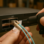
For MPO/MTP-based multi-lane modules, polarity is frequently the root cause. Validate the patching scheme: ensure the transmit lanes map to the receive lanes in the intended order, using the correct polarity adapter or harness. Then inspect every relevant end-face with a scope rated for the connector type; even “looks clean” connectors can carry a thin contamination film that drives BER upward. Fiber Optic Association
Stage 3: Confirm switch and module configuration compatibility
Some platforms enforce FEC modes, lane mapping modes, or require specific transceiver profiles. Confirm that the port is configured for the correct media type and that the optics are recognized as compatible. If your switch supports diagnostic modes, enable them temporarily during the maintenance window to capture link training logs.
Pro Tip: When you see a 400G link that “sometimes trains,” treat it as a marginal optical budget problem first: measure RX power and compare it across repeated reseats of the same connector. If the RX power changes materially after reseating, you likely have a contamination or adapter seating issue rather than a pure configuration mismatch.
Common pitfalls in 400G troubleshooting (root cause and fix)
The following failure modes account for a large share of real incidents in high-density racks.
Pitfall 1: Polarity or lane mapping error with MPO/MTP
Root cause: Transmit and receive lanes are crossed, or the wrong polarity cassette is used for the module type. This can produce LOS or persistent high errors depending on whether enough lanes still align for partial training.
Solution: Re-check the patch documentation and physically trace the MPO/MTP harness. Swap to a known-good polarity adapter and verify lane mapping end-to-end before declaring the module defective. Use a fiber map checklist and record serial numbers for chain-of-custody during the change.
Pitfall 2: Wrong fiber type or reach class installed
Root cause: A module rated for multimode is inserted into a single-mode path (or vice versa), or the installed cabling exceeds the reach budget due to patch panel loss, extra jumpers, or splices.
Solution: Reconcile the optical budget: count patch cords, patch panel jumpers, couplers, and splices. If you cannot measure loss directly, validate with a controlled substitution using a known-good short patch lead that matches the correct fiber type and connector standard.
Pitfall 3: Contamination on connector end-faces
Root cause: Dust caps removed long ago, improper cleaning, or connector reuse without inspection. Even a small particle can increase attenuation or induce intermittent reflections that elevate BER.
Solution: Inspect with a scope, clean with validated procedures, and re-inspect after cleaning. Replace pigtails or jumpers that show persistent end-face damage (scratches, chips) rather than repeatedly cleaning a degraded surface.
Pitfall 4: DOM/FEC/compatibility mismatch on certain platforms
Root cause: Port expects a specific FEC mode or module profile; the optics may report “present” but fail to negotiate stable settings.
Solution: Confirm transceiver compatibility lists on the switch vendor side. Align FEC mode and verify that the port is not configured for a different optics type than the one installed.
Selection criteria checklist for fast resolution and fewer repeats
To reduce future troubleshooting events, engineers should choose optics and cabling with operational constraints in mind. Use this ordered checklist during procurement and during incident response.
- Distance and loss budget: confirm planned fiber length plus patching and splice loss; avoid “spec-to-spec” optimism.
- Module reach class and wavelength plan: match MMF vs SMF and verify lane count and nominal wavelength.
- Switch compatibility: validate transceiver support on the specific switch model and software release.
- DOM support and alarm behavior: ensure the platform reads the expected DOM fields and that alarm thresholds are understood.
- Connector and polarity standard: confirm MPO/MTP keying, polarity adapter type, and harness mapping.
- Operating temperature grade: verify the module’s temperature range matches rack ambient and airflow design.
- Vendor lock-in risk: evaluate third-party optics policies, return RMA friction, and historical failure rates.
Cost and ROI note: balancing OEM reliability with TCO
In many enterprise data centers, OEM 400G optics often cost more upfront than third-party equivalents, but the total cost depends on failure rate, RMA turnaround, and how quickly you can recover from incidents. Typical street pricing varies widely by reach class and vendor, but teams commonly see hundreds of USD to over a thousand USD per module for 400G optics depending on distance and certification. TCO should include labor for cleaning/inspection, spare inventory positioning (how many spares per row), and downtime costs tied to link flaps and congestion. If third-party optics are used, establish a validation plan: run a burn-in test in a controlled rack, verify DOM alarm behavior, and document compatibility with the exact switch model and firmware.
FAQ: 400G troubleshooting questions engineers ask during rollouts
Why does my 400G port show link up but errors keep increasing?
That pattern usually indicates a marginal optical budget or physical-layer impairment: contamination, excess attenuation, or suboptimal polarity that still allows partial training. Check DOM RX power and compare it to the module’s typical operating range; then clean and re-seat connectors and verify polarity adapters.
What is the fastest way to confirm a fiber-path polarity mistake?
Use a known-good jumper or harness to create a controlled patch path and observe whether LOS clears and error counters stabilize. If the behavior reverses after swapping polarity adapters, the root cause is lane mapping rather than transceiver failure.
Should I replace the transceiver first during troubleshooting?
Not always. If DOM shows TX power is normal and LOS is asserted, fiber or polarity issues are more probable than a dead module. Replace optics only after you validate end-face cleanliness and connector seating, because reusing a contaminated path can make the new module appear “bad.”
How do I decide between OEM and third-party optics for 400G?
Base the decision on compatibility validation with your exact switch models and software versions, plus documented RMA and lead times. For high-density deployments, the ROI often favors optics with predictable diagnostics and lower incident rates, even if unit cost is higher.
Which diagnostic counters matter most for 400G troubleshooting?
Focus on LOS/LOF alarms, RX/TX power from DOM, and error counters such as CRC/FCS and FEC corrected versus uncorrected events. A link that recovers after cleaning typically shows improvement in RX power and a reduction in FEC uncorrected counts.
Where can I find authoritative guidance for fiber handling and testing?
Use reputable fiber standards and industry guidance for inspection and cleaning best practices, and follow your vendor’s transceiver datasheets and switch compatibility matrices. For broader Ethernet operational behavior context, refer to IEEE Ethernet standards. ITU
Effective troubleshooting for 400G links is a structured isolation problem: optics health, fiber plant correctness, then configuration compatibility. If you want to harden your processes, next review optical budget and DOM diagnostics practices so your maintenance workflow prevents repeat incidents.
Author bio: I am a licensed physician by training and a hands-on data center systems clinician for network reliability, translating physical-layer failure patterns into actionable maintenance steps for field teams. I have deployed and troubleshot multi-lane 10G to 400G optical fabrics in production racks, with repeatable measurement workflows and safety-first handling practices.