In modern networks, the telecom future is decided in the wiring closet as much as in the architecture deck. This article helps network engineers, procurement leads, and field technicians choose pluggable optics that keep working as line rates climb, optics standards evolve, and power budgets tighten. You will get practical selection criteria, real troubleshooting patterns, and a roadmap mindset for SFP, QSFP, and next-generation coherent deployments.
Why pluggable optics became the telecom future’s control plane

Pluggable optics turned fiber links into “replaceable hardware,” which matters when traffic growth forces frequent upgrades. Instead of redesigning a board, teams can swap a module while keeping the switch or router fabric constant—so long as the host meets the right electrical and optical interfaces. In practice, the telecom future is less about one perfect module and more about maintaining compatibility across vendors, speed grades, and operational temperature ranges. The IEEE 802.3 family of Ethernet PHY standards anchors link behavior, while vendor datasheets define the physical layer details that make or break deployments. [Source: IEEE 802.3 Working Group]
Standards and interoperability you can actually measure
Engineers typically validate pluggable optics by checking compliance with the relevant IEEE 802.3 clause for the target Ethernet rate, then verifying electrical characteristics like transmitter output power and receiver sensitivity. For example, 10GBASE-SR uses multimode fiber and short-reach optics, while 100GBASE-SR4 and 400GBASE-SR4 add lane aggregation and tighter alignment requirements. On the packaging side, the module form factor (SFP, SFP+, QSFP+, QSFP28, QSFP-DD) determines pinout, optical bores, and thermal constraints. Most modern modules also expose Digital Optical Monitoring (DOM) data through an I2C management channel.
Pro Tip: Many “mystery link flaps” trace back to DOM and power class mismatches, not fiber quality. If your switch checks vendor-specific thresholds for diagnostics, a third-party module may pass basic optics tests but fail vendor-specific alarm logic during temperature transients.
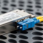
Key module types: SFP to QSFP-DD, and what changes with each step
The telecom future is a ladder of higher rates and higher density. Each rung changes optical reach, lane counts, transceiver power, and how the host switch manages diagnostics. In the field, the decision often boils down to: do you need short-reach multimode, medium-reach singlemode, or coherent long-haul? For most data center and metro aggregation, pluggable direct-detect optics dominate; coherent optics are increasingly common for long-haul and some metro routes where spectral efficiency matters. [Source: ANSI/TIA-568 and vendor optical design guides]
Real-world spec tradeoffs that drive your bill of materials
When you move from 10G to 25G, 40G, 100G, and 200G/400G, the optical budget and lane aggregation become less forgiving. For multimode links, modal bandwidth of the fiber and connector cleanliness can dominate the outcome, especially with OM4 and OM5. For singlemode, the key is choosing the correct wavelength band and ensuring the host supports the module’s optical interface class. Temperature range also matters: a module that works at room temperature can fail during hot-aisle operation if the host’s airflow pattern is different from your lab bench.
Comparison table: choosing direct-detect pluggables for near-term telecom future
Below is a practical comparison of common direct-detect pluggable optics engineers deploy today. Use it as a first-pass filter, then confirm exact support in the host switch compatibility list and the module datasheet. The telecom future increasingly rewards teams who standardize on a limited set of module families that cover multiple upgrade paths.
| Module family (example part) | Data rate | Wavelength | Fiber type | Typical reach | Connector | DOM | Operating temp range |
|---|---|---|---|---|---|---|---|
| SFP-10G-SR (Cisco SFP-10G-SR) | 10G | 850 nm | OM3/OM4 multimode | ~300 m (OM3), up to ~400 m (OM4) | LC | Yes (vendor-specific thresholds) | ~0 to 70 C (check datasheet) |
| SFP+ 10G SR (Finisar FTLX8571D3BCL) | 10G | 850 nm | OM3/OM4 multimode | ~300 m | LC | Yes | ~0 to 70 C (check datasheet) |
| SFP+ 10G SR-85 (FS.com SFP-10GSR-85) | 10G | 850 nm | OM4 multimode | Up to ~400 m (OM4) | LC | Yes | ~0 to 70 C (check datasheet) |
| QSFP28 100G SR4 (example class) | 100G | ~850 nm (multi-lane) | OM4/OM5 multimode | ~100 m typical (varies by spec) | LC (often MPO/MTP on SR4 variants) | Yes | ~0 to 70 C (check datasheet) |
| QSFP-DD 400G SR4 (example class) | 400G | ~850 nm (multi-lane) | OM4/OM5 multimode | ~100 m typical (varies by spec) | MPO/MTP | Yes | ~0 to 70 C (check datasheet) |
Note the pattern: multimode SR is convenient and cost-effective, but it is sensitive to connector hygiene, patch cord quality, and link length. Singlemode pluggables (for example, LR/ER classes at 1310 nm or 1550 nm) are less sensitive to modal effects but introduce wavelength-specific compatibility and dispersion considerations. [Source: IEEE 802.3 and typical vendor transceiver datasheets]
Deployment scenario: a metro aggregation upgrade without rewiring
Consider a metro aggregation site with 3-tier topology: 48-port 10G ToR switches feeding 8-port 100G aggregation uplinks, then 400G spine links. The operator plans to migrate from 10G to 25G and from 100G to 200G/400G over 18 months, but they cannot re-pull fiber. In the existing plant, they have OM4 multimode trunks for short distances (under 100 m) and singlemode for longer corridors (over 1 km). During each maintenance window, they replace optics only: swapping 10G SR SFP+ modules with 25G SR modules where the host supports that PHY, then later moving aggregation uplinks to 100G/200G SR4 or singlemode variants. Field validation includes checking DOM thresholds in the switch logs and running link margin tests after each replacement to catch marginal connectors before traffic shifts.
Selection checklist for the telecom future: decisions that prevent future outages
When choosing pluggable optics, engineers should treat selection as a compatibility and operations exercise, not a catalog exercise. The following ordered checklist reflects what teams weigh during procurement and pre-deployment testing.
- Distance and fiber plant reality: confirm exact patch cord lengths, connector types, and whether fiber is OM3, OM4, or OM5 (multimode) or standard OS2 (singlemode).
- Target Ethernet PHY per IEEE 802.3: align the module class to the expected link mode (for example, SR, SR4, LR, ER) and lane aggregation behavior.
- Switch and chassis compatibility: verify the host’s optic compatibility list, including firmware-reported supported transceiver families.
- DOM behavior and threshold checks: ensure the host accepts the module’s diagnostic interface and does not flag “out of tolerance” values during normal temperature drift.
- Operating temperature and airflow: confirm the module’s rated range and test in the actual airflow pattern of hot aisle or cold aisle deployments.
- Vendor lock-in risk and supply continuity: evaluate whether OEM-only modules are required, and if third-party options exist with documented compatibility.
- Connector strategy and hygiene tooling: standardize LC vs MPO/MTP usage and ensure you have inspection scopes and cleaning kits sized for the connector type.
- Power budget and thermal headroom: check module power draw and host thermal design limits, especially in high-density QSFP-DD ports.
Common pitfalls and troubleshooting in pluggable optics work
Even disciplined teams run into failures. These are the most common field patterns, with root causes and the fixes that typically restore service quickly.
“Link comes up, then flaps under heat”
Root cause: transceiver temperature behavior and host alarm thresholds disagree; the module may be within spec optically but triggers DOM-based warnings during hot-aisle spikes. Solution: compare switch log events for DOM alarms, verify module temperature range, and test with a known-good transceiver from the same family. If you use third-party modules, confirm the host firmware revision supports their diagnostic format. Update the host firmware only after a controlled pilot, since optics compatibility can change between releases.
“Passes at install, fails after a few patch cord changes”
Root cause: connector contamination or micro-scratches from repeated handling; multimode SR links are especially sensitive at 850 nm. Solution: inspect and clean both ends using approved swabs and lint-free wipes, then re-test. Replace patch cords rather than repeatedly cleaning the same damaged ends. Store dust caps and use connector covers during any maintenance window.
“Wrong wavelength band or wrong reach class”
Root cause: a module is physically compatible but logically incorrect for the intended link budget, such as using an SR class where an LR/ER singlemode class is required. Solution: verify wavelength and reach class against the fiber type and measured attenuation. Use the optical budget worksheet and confirm the host port expects that class. For singlemode, ensure you do not mix modules that use different nominal center wavelengths or that the host supports the module’s optical interface.
Cost and ROI note: balancing OEM reliability with future-proofing
Pricing varies by speed and connector complexity, but realistic procurement ranges help planning. In many markets, 10G SR SFP/SFP+ modules often cost roughly tens of dollars to low hundreds depending on OEM vs third-party and certification status, while 100G and 400G pluggables can range from several hundred to well over a thousand dollars per module, especially when coherent or higher-spec components are involved. Total cost of ownership is not just purchase price: failure rate, downtime labor, and maintenance window scheduling can dominate TCO. OEM optics may reduce compatibility risk with strict DOM threshold enforcement, while third-party optics can cut unit cost if you validate them in a pilot and lock firmware versions. For the telecom future, the best ROI usually comes from standardizing a small set of module families that match your migration path and from investing in connector hygiene tooling that prevents avoidable returns.
FAQ: telecom engineers ask about pluggable optics in the telecom future
Which pluggable type is most future-friendly for data center upgrades?
For many operators, QSFP28 and QSFP-DD families are more future-friendly than older SFP/SFP+ because they align with higher-density port scaling and modern switch designs. However, “future-friendly” only holds if the host firmware and compatibility list explicitly support the module family you plan to standardize.
Can I mix OEM and third-party optics safely?
Often yes, but it is not universal. You must validate compatibility with your exact switch model and firmware, and you must confirm DOM thresholds and alarm behavior. Run a controlled pilot with representative temperatures and fiber lengths before scaling to production.
What causes receiver errors even when fiber looks clean?
Receiver errors can come from marginal link budgets, excessive patch cord loss, or connector geometry issues that cleaning alone cannot fix. Verify the patch cord attenuation, check for damaged ferrules, and confirm the module reach class matches the fiber plant and measured attenuation.
How do I plan for the telecom future if rates will change mid-life?
Build a migration plan that pairs port capabilities with a stable transceiver family strategy. Standardize on module classes that map to multiple target speeds where possible (for example, staying within the same connector ecosystem and DOM expectations), and keep your firmware change process controlled.
Why do some links fail only after a firmware update?
Firmware updates can change optics diagnostics thresholds, supported transceiver lists, or PHY behavior. To reduce risk, test firmware changes in a lab or pilot cluster, and keep a rollback plan that includes known-good optics inventory.
Is multimode still worth it for the telecom future?
Multimode remains cost-effective for short reach, especially in data centers and metro where distances are typically under the SR limits. The key is disciplined connector hygiene, correct fiber type (OM4/OM5), and selecting modules whose optical budgets match your measured plant loss.
If you want your telecom future to be resilient, treat pluggable optics as an operational system: compatibility, diagnostics, hygiene, and thermal reality all matter. Next, explore how to evaluate fiber link budgets for pluggable optics to turn “it should work” into measured margin.
Author bio: I have deployed and troubleshot pluggable optics in live data centers and metro aggregation sites, validating DOM alarms and link margins during cutovers. I write from hands-on field experience with IEEE 802.3-aligned PHY behavior and vendor datasheet constraints.