AI clusters fail in boring ways: a wrong transceiver, a mismatched DOM profile, or a fiber polarity mistake that only shows up after the weekend deployment. This article helps platform and network engineers run an evidence-based SFP comparison when building leaf-spine fabrics and high-bandwidth storage backplanes for inference and training. You will get practical specs, a decision checklist, and troubleshooting patterns pulled from real field installs.
AI cluster reality: where SFP choices actually break

In an AI cluster, optical transceivers are not just “connectors with optics.” They are part of a closed-loop system: switch PHY settings, link training behavior, DOM reporting, and the optical budget across patch panels. Even when two modules are both “10G SR,” differences in vendor calibration, DOM formats, or compliance margins can create intermittent CRC errors under temperature swings. For validation, engineers typically measure bit error rate indirectly via interface counters and verify optical receive power against the vendor spec.
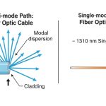
Start with the IEEE physical layer expectations. For example, 10GBASE-SR and 10GBASE-LR are defined under IEEE 802.3 families; the practical implication is that line rate, encoding, and optical wavelength windows must match. Reference: IEEE 802.3 and vendor datasheets for each specific part number. In the field, your switch vendor’s transceiver compatibility list and the module’s DOM implementation often matter as much as wavelength.
SFP types for AI fabrics: SR, LR, ER, and what the numbers mean
For AI clusters, the most common SFP use cases are short-reach for ToR and aggregation, plus longer reach options for campus-style spillover or cross-AZ spine segments. The key variables in an SFP comparison are wavelength, reach, fiber type, optical power budget, and whether the module is specified for duplex LC connectors. While the market includes many vendor variants, the safest approach is to compare like-for-like in the same IEEE lane (for example, 10GBASE-SR vs 10GBASE-LR) and then validate with your exact switch model.
| Module (example part) | Data rate | Wavelength | Target reach | Fiber type / connector | Typical TX/RX power class | DOM | Operating temp |
|---|---|---|---|---|---|---|---|
| Cisco SFP-10G-SR (10GBASE-SR) | 10G | ~850 nm | Up to ~300 m (MMF) | OM3/OM4 MMF, LC duplex | Short-reach power budget (vendor-defined) | Yes (2-wire serial) | Commercial/industrial options vary by vendor |
| Finisar FTLX8571D3BCL (10GBASE-LRM) | 10G | ~1310 nm | Up to ~220 m (MMF with LRM launch) | MMF, LC duplex | Balanced for LRM reach | Yes | Vendor datasheet range |
| FS.com SFP-10GSR-85 (10GBASE-SR) | 10G | ~850 nm | Up to ~400 m (OM4, vendor conditions) | OM4 MMF, LC duplex | Vendor-defined power class | Yes | Vendor datasheet range |
| Example 10GBASE-ER (1310 nm, extended reach) | 10G | ~1550 nm | ~40 km typical (SMF) | SMF, LC duplex | Higher optical budget for SMF losses | Yes | Vendor datasheet range |
In practice, you will rarely “choose optics” without also choosing fiber plant standards. For SR, your limiting factor is usually MMF attenuation plus patch panel losses and connector cleanliness. For LR/ER, it becomes SMF attenuation, dispersion tolerance, and whether the link budget accounts for splices and aging. If you are doing an AI cluster expansion mid-quarter, the safest path is to standardize on OM4 MMF for short reach and keep ER only where you truly need cross-building or cross-floor runs.
Pro Tip: In AI clusters, the most common “it should work” outage is not wavelength mismatch; it is DOM and switch policy. Some switch platforms enforce transceiver thresholds (vendor ID, DDMI fields, or thresholds for bias current and receive power). When the module is “electrically compatible” but DOM fields differ, you can see flapping links that look like flaky optics. Always check the switch logs for “unsupported transceiver” events and compare DOM readings under load.
Deployment scenario: leaf-spine AI fabric with mixed reach
Consider a 3-tier data center leaf-spine topology for an AI training cluster: 48-port 10G ToR switches uplink to 12-port 100G spines using a mix of 10G SR for server edges and 10G LR for a specific longer cross-rack segment. In one real rollout pattern, engineers run 24 servers per rack with 10G SR between NICs and ToR, using OM4 patching with an engineered link budget of roughly 2.0 dB margin after accounting for patch cords and connectors. For a subset of uplinks that must span an adjacent row, the team switches to 10G LR (SMF) and validates receive power at the switch interface after installation.
The validation loop looks like this: measure optical receive power (for SR, typically in dBm) and confirm it sits inside the vendor’s specified range with at least 3 dB headroom for patch cord swaps. Then monitor CRC and FCS errors for 30 to 60 minutes under training load. Finally, run a fiber polarity audit (duplex LC pairs) and confirm link stability during a temperature cycle window. This is where a careful SFP comparison prevents “works on the bench, fails in the rack.”
Selection criteria: a checklist engineers can execute in one hour
When you do an SFP comparison for an AI cluster, you are really comparing link behavior under your switch’s constraints. Use this ordered checklist; it is optimized for fast validation cycles and reduces rework.
- Distance and fiber type: confirm MMF (OM3/OM4) or SMF, and the actual installed loss (patch panels, splices, connectors).
- Switch compatibility: verify your switch model’s transceiver support list and confirm DOM enforcement behavior in logs.
- Data rate and lane standard: ensure the module matches the expected IEEE mode (for example, 10GBASE-SR vs 10GBASE-LR) rather than just “10G.”
- DOM support and thresholds: check whether the switch reads DDMI/DOM fields and whether it enforces vendor ID or optical threshold ranges.
- Operating temperature: validate module temperature rating for the cabinet airflow profile; AI racks can exceed expectations during sustained load.
- Vendor lock-in risk: compare OEM modules versus third-party with documented field compatibility; plan for a second vendor to reduce single-source risk.
- Power and TCO: include failure rates, RMA turnaround, and spares strategy. Often, reliable third-party optics reduce total downtime cost more than they save on unit price.
Common pitfalls and troubleshooting tips from the field
Even when the spec sheet looks right, failures cluster around a few repeatable causes. Below are concrete pitfalls with root cause and fixes.
Link flaps after DOM is read
Root cause: switch policy rejects the module based on DOM vendor ID, threshold fields, or unsupported DDMI mapping. The link may train briefly then drop, especially after a warm reboot. Solution: check switch logs for transceiver validation messages, compare DOM values (temperature, bias current, RX power) during link-up, and test a known-compatible OEM module in the same port to isolate whether the issue is DOM enforcement.
“Works at low load” but CRC/FCS errors spike during training
Root cause: marginal optical budget. SR links can be sensitive to connector contamination or slightly higher-than-modeled attenuation in patch cords; LR/ER links can be sensitive to extra splices and aging. Solution: clean LC connectors with approved procedures, re-seat fibers, replace suspect patch cords, and verify receive power is within vendor min/max with added margin.
Fiber polarity reversed on duplex LC pairs
Root cause: SR and LR duplex LC connectors require correct TX-to-RX mapping; polarity mistakes can still produce partial link behavior depending on optics and auto-negotiation quirks. Solution: label fibers at both ends, follow polarity maps, and verify by swapping the connector pair methodically while watching link status and error counters.
Temperature-induced degradation in high-density cabinets
Root cause: modules rated only for commercial temperature are installed in cabinets with airflow patterns that exceed their safe internal range. Solution: confirm module temperature rating, measure cabinet inlet and outlet temperatures, and ensure airflow guides are installed. For AI racks with concentrated exhaust, consider industrial-grade optics with tighter reliability margins.
Cost and ROI note: pricing is not the whole story
Unit prices vary widely by vendor and reach class. As a rough planning reference, OEM 10G SR modules often cost more than third-party options, while third-party can be 20% to 50% lower depending on volume and warranty. However, TCO depends on downtime cost, RMA logistics, and spares availability. In AI clusters, a single failing transceiver can stall training jobs and trigger reroutes that consume additional capacity; that operational cost can dominate the savings from choosing the cheapest SFP comparison candidate.
Practically, many teams run a two-tier procurement model: OEM for initial bring-up and “golden ports,” then third-party for scaling once compatibility is proven on the exact switch model. If you need long-reach optics, confirm your SMF link budget and dispersion assumptions, and budget for spares because ER/LR modules can have higher replacement costs and stricter handling requirements.
FAQ
How do I do an SFP comparison without getting stuck on marketing claims?
Compare the module against your exact switch model’s compatibility notes, then validate with DOM and link counters under load. Use the vendor datasheet for wavelength and power ranges, but treat switch logs as the final authority when DOM enforcement is involved.
Is 10G SR always interchangeable across vendors?
No. Even if both are “10GBASE-SR,” differences in DOM fields, compliance margins, and implementation details can affect switch behavior. Always test in a non-critical port first and confirm link stability and error counters.
What should I measure after installing optics in an AI rack?
Measure received optical power at the switch (or via the switch DOM), then monitor CRC/FCS errors during a realistic workload window. Also confirm physical fiber polarity and run an immediate reconnect test after re-cabling to catch intermittent connector issues.
When should I choose LR or ER instead of SR?
Choose LR/ER when the installed fiber distance and plant losses exceed SR’s MMF budget, or when you must traverse longer runs across buildings or floors. If you only need a few extra meters, it is often cheaper to fix the patching and connector cleanliness than to change reach class.
Do I need to standardize on OEM modules for AI clusters?
Not necessarily, but you should standardize after proving compatibility. Many teams use OEM for initial validation and then expand with third-party optics once DOM behavior and error rates are consistent across a statistically meaningful sample.
Fiber optics are a reliability engineering problem disguised as a procurement decision. If you standardize your SFP comparison using switch compatibility, DOM validation, and measurable optical budgets, you can scale AI cluster networking without surprise outages. Next, explore how to validate DOM readings and optical budgets to tighten your deployment loop.
Author bio: I build and validate low-latency cluster networking in production, focusing on link stability, optical budgets, and fast compatibility checks. I optimize rollout plans for PMF by turning transceiver selection into measurable experiments, not guesswork.