When an SFP link flaps, the root cause is often not “bad fiber,” but how TX Disable and RX LOS interact with switch optics, power budgets, and alarms. This article helps network engineers, field techs, and data center operators design safer change windows and faster fault isolation for optical signal management. You will get practical compatibility checks, a spec comparison table, and troubleshooting steps that map directly to common failure modes in production.
Why TX Disable and RX LOS decide whether a link stays up
In SFP-based Ethernet, the module continuously monitors receive conditions. When the photodiode input falls below a defined threshold, the module asserts RX LOS (Loss of Signal), which typically drives the host switch to log alarms and may influence link training behavior. Separately, TX Disable is a host-controlled or internally managed mechanism that can shut down transmitter output to prevent unstable bursts, eye degradation, or unintended radiation during faults.
From a control-systems perspective, you want deterministic behavior: when RX power is insufficient, the system should stop transmitting (or stop interpreting traffic) in a consistent way. In practice, the exact behavior depends on the SFP electrical interface (commonly defined by SFF-8472 for diagnostic and control signals) and the switch vendor’s implementation of LOS handling. For standards context, Ethernet optics performance expectations align with IEEE 802.3 link requirements and the optics’ own datasheet thresholds. [Source: IEEE 802.3™ (optical PHY requirements)] [Source: SFF-8472 (digital diagnostic and control interface)]
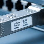
Pro Tip: In the field, many “random” link flaps are actually a timing mismatch: the switch reacts to RX LOS faster than the module releases TX Disable after power recovers. If you can, capture DOM readings and syslog timestamps together; the ordering often reveals whether you need a host-side alarm threshold tweak, a different optic revision, or a fiber cleaning workflow change.
SFP optical signal management specs that matter for TX Disable and LOS
Not all SFPs expose the same diagnostics or interpret LOS thresholds the same way. For stable optical signal management, engineers should compare wavelength, reach class, optical power range, receiver sensitivity, and the module’s documented LOS assertion/deassertion behavior. Pay special attention to whether the module provides digital diagnostics (DOM) and whether the switch supports reading those registers reliably.
Below is a practical comparison you can use when selecting 10G SFP optics for enterprise or data center links. Exact LOS thresholds vary by vendor and revision, so treat these as representative ranges and verify against the specific datasheet for the exact part number you plan to deploy.
| Parameter | 10G SR SFP (850 nm MMF) | 10G LR SFP (1310 nm SMF) | Typical Relevance to TX Disable/RX LOS |
|---|---|---|---|
| Wavelength | 850 nm | 1310 nm | Impacts fiber attenuation, connector loss budget, and receiver margin |
| Target reach | Up to 300 m (OM3/OM4 class varies) | Up to 10 km | Determines whether link budget is safely above LOS threshold |
| Receiver sensitivity (typical) | ~ -10 to -12 dBm | ~ -14 to -18 dBm | Higher sensitivity gives more headroom against dirty connectors |
| TX optical power (typical) | ~ -1 to +1 dBm | ~ -3 to 0 dBm | Low TX power increases probability of RX LOS assertion |
| Connector type | LC duplex (typical) | LC duplex (typical) | Connector geometry strongly affects short-reach loss spikes |
| DOM support | Common: yes (vendor dependent) | Common: yes (vendor dependent) | Enables real-time TX/RX power correlation to LOS events |
| Operating temperature | Commercial or industrial variants | Commercial or industrial variants | Temperature drift can reduce optical margin and trigger LOS |
| TX Disable behavior | Host or module controlled | Host or module controlled | Prevents emission during faults and stabilizes link recovery |
For concrete part references used in many deployments: Cisco-branded optics like Cisco SFP-10G-SR and third-party compatible optics such as Finisar FTLX8571D3BCL and FS.com SFP-10GSR-85 often provide DOM and predictable optical power classes, but you must confirm switch compatibility and exact DOM map support. [Source: Vendor datasheets for Cisco SFP-10G-SR, Finisar FTLX8571D3BCL, FS.com SFP-10GSR-85]

Deployment scenario: preventing flap storms in a leaf-spine fabric
Consider a 3-tier data center leaf-spine topology with 48-port 10G ToR switches at the leaf layer and 2 uplinks per server. Each rack uses patch panels with LC duplex jumpers routed through overhead trays. During a maintenance window, a tech swaps 12 SFP SR optics (850 nm, MMF) to replace aging inventory. Within minutes, several links flap when a subset of connectors show intermittent contamination and the received power hovers near the LOS threshold.
In this scenario, stable optical signal management requires you to correlate: (1) the switch’s RX LOS alarms, (2) module DOM values for RX power and TX power, and (3) the timestamps of interface up/down events. When RX power dips below sensitivity, RX LOS asserts; the switch may stop treating the link as valid while the module’s transmitter may remain enabled until TX Disable is applied by the host or by the module’s internal logic. The fix is usually operational: clean connectors with proper inspection, replace jumpers with known-good loss, and ensure the host’s alarm handling does not repeatedly trigger a rapid disable/enable loop.
Selection checklist for stable TX Disable and RX LOS behavior
Use this ordered decision checklist before you standardize optics or during a migration from one vendor family to another. It is designed to reduce LOS events and prevent unpredictable transmitter behavior.
- Distance and link budget: confirm the planned fiber type (OM3/OM4 or SMF), estimated worst-case attenuation, and connector/mating loss. Stay comfortably above receiver sensitivity.
- Switch compatibility: validate that the switch supports the optic electrically and interprets alarms correctly. Some platforms require specific DOM or vendor ID behavior.
- DOM support and visibility: prefer optics that expose reliable TX bias current, TX power, and RX power via digital diagnostics so you can prove margin before LOS.
- Documented LOS thresholds: check the exact datasheet for LOS assert/deassert range and any hysteresis. If the vendor does not publish it, plan for conservative margin.
- Operating temperature: confirm whether the module is commercial (0 to 70 C typical) or industrial (-40 to 85 C) and match it to your ambient and airflow realities.
- TX Disable control model: confirm whether TX Disable is host-controlled, module-controlled, or both, and how long the module takes to re-enable after fault recovery.
- Vendor lock-in risk: if you use third-party optics, test burn-in behavior and alarm patterns. Keep at least one known-good reference optic for rapid rollback.

Common pitfalls and troubleshooting that actually resolves LOS events
Below are practical failure modes seen during optical signal management work. Each includes the likely root cause and a targeted fix that reduces repeat outages.
Pitfall 1: LOS triggered by connector contamination, not fiber attenuation
Root cause: Dirty LC ferrules or patch panel adapters can cause sudden loss spikes that push RX power below sensitivity, leading to RX LOS assertions. This often presents as intermittent flaps rather than a permanent down link.
Solution: Inspect with a fiber microscope, clean with lint-free methods and approved wipes, and re-test with a known-good reference optic. If you see repeated failures in the same patch location, replace the patch cord or adapter.
Pitfall 2: Margin too tight for real-world worst case
Root cause: Teams sometimes design for “typical” loss, but the real deployed path includes extra patch panel mated pairs, aging connectors, and temperature effects. RX power then hovers near LOS thresholds, creating rapid recoveries.
Solution: Use DOM to measure actual RX power at the switch port during steady state. Add buffer by moving to a higher-budget optic class or reducing the number of mated connections.
Pitfall 3: Switch alarm behavior causes rapid enable/disable oscillation
Root cause: If the host reacts to LOS quickly and repeatedly toggles transmitter state (explicitly via TX Disable or implicitly via interface resets), transient recoveries can trigger repeated flapping.
Solution: Capture syslog and DOM timestamps, then adjust operational thresholds or disable aggressive port reset policies if your platform allows it. Validate with a controlled test: a single port, one fiber path, known-good optics.
Pitfall 4: DOM incompatibility or misread diagnostics
Root cause: Some third-party optics provide DOM data but not in the exact mapping the switch expects, leading to misleading “low power” alarms or missing visibility that delays diagnosis.
Solution: Confirm DOM register reads during commissioning. Keep a reference optic and compare reported TX/RX power values across the same port.

Cost and ROI: what optics should cost, and where TCO hides
Price varies by brand, reach class, and certification. In many markets, 10G SR SFP optics commonly fall in a rough range of $30 to $120 each, while higher-spec or enterprise-certified optics can cost more; third-party options may be cheaper but require compatibility validation. Over a year, the biggest TCO drivers are not purchase price alone: they include labor for troubleshooting, downtime risk from flaps, and the operational cost of repeated cleaning and re-cabling.
ROI improves when you standardize on optics with dependable DOM and predictable alarm behavior, because you reduce mean time to repair. A practical approach is to stock a small set of known-good optics for rollback and track failure rates by rack/patch panel location, not just by optic serial number. For clinical safety mindset: treat optics like precision instruments; mishandling connectors during swaps is a leading cause of repeat failures.
FAQ: TX Disable, RX LOS, and optical signal management decisions
How do I confirm TX Disable is working as expected on my switch?
Check whether the switch can explicitly control transmitter state via the SFP interface and whether it logs TX disable events. Then validate with DOM readings: TX power should drop during disable and recover after the specified re-enable delay. If you cannot correlate those changes, assume the platform may not expose the control path you expect.
What RX LOS behavior should I treat as a warning versus a real outage?
Isolated, brief LOS assertions during transients can be benign, but repeated toggling with interface flaps indicates margin issues or intermittent contamination. Prioritize patterns where RX power is near the sensitivity boundary and recovers slowly. Use alarm hysteresis and syslog timestamps to avoid overreacting to single events.
Are third-party optics safe for optical signal management in production?
They can be, but you must validate switch compatibility, DOM mapping, and alarm patterns during commissioning. Deploy a controlled pilot and compare TX/RX power readings and LOS timing against a reference optic. If your switch supports strict vendor ID checks, plan for that constraint early.
Does temperature affect LOS thresholds enough to cause link flaps?
Temperature can change laser bias and photodiode response, reducing optical margin. In high-density racks with inconsistent airflow, this effect is more noticeable. If you see LOS events clustered by time of day or thermal zones, validate module operating temperature and airflow before replacing optics.
What is the fastest troubleshooting sequence for intermittent SR link flapping?
Start with fiber inspection and cleaning at both ends, then check DOM RX power trends during a flap window. Next, verify the fiber path loss budget and reduce the number of mated adapters if needed. If the problem persists, swap in a known-good reference optic to isolate whether the failure follows the optic or the fiber path.
Which standards should I reference when documenting optics behavior?
For Ethernet PHY requirements, use IEEE 802.3 guidance. For SFP digital diagnostics and control signal concepts, use SFF-8472 documentation and the specific optic datasheet you deploy. Document your switch vendor’s LOS handling specifics because they can differ even when optics are compliant.
Stable optical signal management is achievable when you treat TX Disable and RX LOS as part of an end-to-end control loop