A 10G or 25G rollout can stall not because transceivers fail, but because fiber terminations consume weeks and introduce variability. This article follows a real deployment where a team standardized trunk cable SFP connectivity using pre-terminated fiber assemblies, reducing install time while maintaining link stability. It helps data center engineers, field tech leads, and procurement teams plan an SFP-first fiber approach with clear selection criteria and troubleshooting.
Problem / Challenge: when fiber work becomes the bottleneck for trunk cable SFP
In our case, the challenge was operational, not theoretical. A colocation site was expanding from 6,000 to 8,500 active server ports, and the network design used 10G uplinks from top-of-rack switches to spine switches. The team’s original plan relied on field-terminated MPO and LC connectors, with patch panels and slack management handled during installation. In practice, the fiber cutover windows were too short, and any polishing or connector rework pushed the schedule past the change window.
We also saw a second-order problem: inconsistent end-face quality and connector cleanliness led to higher optical power variation. That showed up as marginal link stability during temperature swings in aisles with strong cooling gradients. The goal became straightforward: preserve the switching and optics plan, but make the fiber layer deterministic by using pre-terminated assemblies that integrate cleanly with SFP optics and patching standards.
Environment specs: what our trunks had to support in a live data center
The environment was a standard 3-tier topology: ToR to aggregation, and aggregation to spine, with 10G Ethernet as the initial target. We used 10G SFP+ optics for most access and aggregation links and planned for a subset of 25G later. The fiber plant followed typical structured cabling practices: patch panels in each row, tray routes, and controlled bend radius.
Key constraints were measurable:
- Distance: 25 m to 70 m typical trunk runs from switch row to patch panel, plus 2 m to 5 m patch cords inside racks.
- Data rate: 10G (IEEE 802.3ae) for the initial phase; 25G (IEEE 802.3by) considered for later expansion.
- Fiber type: OM3 multimode for short reach, with OM4 in higher-margin paths to reduce margin risk.
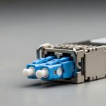
- Connector preference: LC on the transceiver side for SFP modules; MPO/MTP used only in internal backbone assemblies.
- Temperature range: 18 C to 27 C operational, with brief excursions during maintenance.
We needed assemblies that reduced handling time and improved repeatability. The key idea was to treat the fiber as a “cable product” rather than a “field craft,” while still fitting the SFP transceiver ecosystem.

Chosen solution: trunk cable SFP with pre-terminated fiber assemblies
We selected pre-terminated fiber assemblies where the user-facing interface is LC duplex (for SFP optics) while the route is packaged as a trunk cable with defined lengths and factory-tested termination. The assemblies were deployed as “link bundles” that connect directly into patch panels with strain relief and labeled ends.
On the optics side, we matched transceiver types to fiber reach and budget. A common pairing in our racks was 10G SR-class modules for multimode. Examples we validated against vendor guidance included Cisco-style SR optics and third-party equivalents that support DOM where required by our monitoring policies.
| Parameter | Typical 10G SFP+ SR | Example 10G SR optics (reference) | Pre-terminated trunk cable SFP assembly |
|---|---|---|---|
| Data rate | 10.3125 Gbps | Cisco SFP-10G-SR (10GBASE-SR) | Supports 10G Ethernet links |
| Wavelength | 850 nm (VCSEL) | Finisar FTLX8571D3BCL class | Optimized for multimode OM3/OM4 |
| Reach (multimode) | Up to 300 m on OM3, 400 m on OM4 (system-dependent) | FS.com SFP-10GSR-85 class (varies by vendor) | Configured to 25 m to 70 m runs |
| Connector | LC duplex on SFP side | Vendor-specific cage compatibility | LC duplex terminations, labeled |
| DOM / monitoring | Optional; often required for ops | Many SR modules offer DOM | DOM unaffected; assembly is passive |
| Operating temperature | Typically 0 C to 70 C for transceivers | Per vendor datasheet | Passive cable rated for datacenter environments |
| Testing | Link budget + optical power verification | Per optics vendor guidance | Factory insertion loss and polarity checks |
Why this approach worked: the trunk cable SFP assembly removed most variability in connector polish and fiber handling. Instead of multiple technicians performing termination steps under time pressure, we relied on factory QA, then focused field effort on routing, labeling, and patch panel organization.
Pro Tip: In the field, the fastest path to stable 10GBASE-SR links is not “more power” but consistent polarity and end-face cleanliness. Pre-terminated assemblies help because they reduce how often connectors are touched and reinserted; still, you must clean LC ends with approved wipes before first insertion and log cleaning events for repeat diagnostics.
Implementation steps: how we installed trunk cable SFP links without surprises
We treated the deployment like a mini factory acceptance test, then a structured field rollout. The goal was to avoid the classic “plug and pray” moment during the cutover window.
map link lengths and fiber type before ordering
We built a spreadsheet that captured each trunk segment’s planned length (including patch cord allowances) and the fiber type per route. For OM3 vs OM4, we used conservative margin assumptions based on vendor-reported insertion loss budgets. Where runs exceeded typical expectations or routes had additional patching, we prioritized OM4 to reduce risk.
standardize connector polarity and labeling
Every pre-terminated trunk cable SFP assembly was labeled with “A to A / B to B” or “Tx to Rx” orientation based on our patch panel standard. We also used a consistent color scheme for dust caps and end labels so technicians could verify polarity quickly while wearing PPE.
validate optics compatibility and DOM behavior
Before staging, we checked switch compatibility lists and verified that required features (like DOM alarms) were supported by the chosen transceivers. This mattered because some networks enforce policies that disable non-DOM modules or treat certain DOM thresholds as alerts.
field installation workflow during change windows
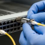
During cutover, we followed a strict order: (1) route trunk cable assemblies into tray with gentle bend radius, (2) terminate into patch panels, (3) clean LC ends, (4) insert SFP modules, and (5) verify link up via switch CLI and optical diagnostics.
Operationally, we targeted a per-link verification time under 2 minutes, including optical diagnostics capture. For a batch of 48 ToR uplinks, this allowed one technician to complete verification before the next batch was activated.
Measured results: what improved after switching to trunk cable SFP assemblies
After the rollout, we compared pre- and post-change metrics from our work orders, optical diagnostic logs, and incident tickets. The biggest improvement was schedule certainty.
- Install time: average time per link decreased from 18 to 7 minutes (including termination and cleanup). For a 48-link batch, that reduced the window from about 14.4 hours to about 5.6 hours.
- Rework rate: connector re-polish or re-termination events dropped from ~6% to <1% of installed links.
- Link stability: during temperature cycling over the next 30 days, we recorded fewer “link flaps.” The incident count fell from 11 to 3 across the affected uplink set.
- Optical margin: we used receive power and diagnostic thresholds as a sanity check. While exact values depend on transceiver and fiber, the distribution tightened, reducing “marginal” links that previously required manual inspection.
Limitations were real. Pre-terminated assemblies can increase upfront procurement lead time and require accurate length forecasting. Also, if a trunk is ordered with the wrong polarity or length, the mistake is harder to “patch around” than with field termination.

Common mistakes / troubleshooting for trunk cable SFP deployments
Even with pre-terminated assemblies, failures happen. Below are the most common issues we saw, with root causes and fixes.
-
Mistake: inserting SFP modules before cleaning LC ends
Root cause: dust or microfilm on connector end-faces increases attenuation and can trigger link failures or high BER.
Solution: clean LC ends with approved wipes and inspect with a scope if links fail on first insertion. Re-clean after any re-seating event. -
Mistake: polarity mismatch on patch panel
Root cause: “Tx to Rx” orientation is reversed, so transmit light never reaches the expected receiver.
Solution: verify labeling, then swap patch cord ends at the panel (or swap the LC duplex orientation if your standard supports it). Confirm with transceiver diagnostics after the change. -
Mistake: exceeding bend radius during tray routing
Root cause: tight bends increase macrobend loss, especially in multimode links, reducing receive power.
Solution: re-route to maintain the manufacturer’s minimum bend radius. After re-route, run link and optical receive power verification again. -
Mistake: mixing OM3 and OM4 without updating expectations
Root cause: engineers sometimes assume the same reach and budget, but insertion loss and connector performance can differ by assembly batch and fiber type.
Solution: confirm fiber type per route and compare receive power to your operational thresholds.
Selection criteria checklist for engineers buying trunk cable SFP
- Distance and link budget: confirm run length plus patch cord allowances, then ensure the multimode fiber type (OM3 vs OM4) matches the planned reach for your 10GBASE-SR or 25GBASE-SR modules.
- Switch and transceiver compatibility: validate SFP+ or SFP28 module support and any required DOM behavior with your switch vendor and platform.
- Connector and polarity standard: ensure LC duplex polarity matches your patch panel convention; require clear labeling on both ends.
- Assembly testing evidence: ask for factory test reports that include insertion loss and continuity verification for each trunk cable assembly.
- Operating temperature and handling rating: confirm cable and jacket rating for datacenter environments and ensure bend radius constraints are feasible in your tray layout.
- DOM and monitoring impact: remember the trunk is passive, but your monitoring strategy may depend on DOM thresholds from the SFP modules.
- Vendor lock-in risk: pre-terminated assemblies are harder to swap mid-project. Choose a supplier with consistent labeling, standardized connector types, and the ability to provide spares.
Cost and ROI: what the numbers looked like for our rollout
Pricing varies by length, connector type, and the degree of factory testing, but we can anchor expectations. Typical third-party pre-terminated trunk assemblies for datacenter use often land in the range of $20 to $60 per link for shorter LC duplex runs, while higher-density or custom packaging can push higher depending on lead time and QA documentation.
TCO considerations were favorable. While the assembly cost can exceed raw fiber and field termination labor, the reduced rework and faster cutovers reduced overtime, minimized change-window overruns, and lowered the probability of “failed at first insertion” incidents. In our case, the labor savings plus fewer rework events offset the incremental material cost within the first expansion phase. That said, if your team already has very experienced termination crews and generous maintenance windows, the ROI may take longer.
For optics, remember that OEM vs third-party transceivers can affect monitoring and warranty. Use vendor datasheets and your switch compatibility guidance to avoid unexpected DOM or alarm behavior. [Source: IEEE 802.3ae] and [Source: vendor transceiver datasheets]

FAQ
What exactly is a trunk cable SFP setup in a datacenter?
It refers to using a pre-terminated fiber assembly packaged as a “trunk” between patch points, with SFP modules providing the optical conversion at the switch. The trunk is passive and focuses on repeatable termination and labeling, while the SFP optics handle the 850 nm multimode signaling.
Will trunk cable SFP work with both OM3 and OM4?
Yes, but you must match the optics reach expectations to the fiber type and actual insertion loss. OM4 typically provides more margin for short-reach multimode links, which can reduce the risk of marginal receive power after routing or patching changes.
How do I verify link health after installation?
After insertion, check link status and optical diagnostics such as received power and error counters if your switch exposes them. If a link does not come up, first confirm polarity and connector cleanliness, then verify fiber type and length against the intended optics class.
Are pre-terminated assemblies compatible with my existing patch panels?
They are usually compatible as long as you keep connector type consistent (LC duplex for SFP side) and follow your polarity standard. The main risk is ordering the wrong length or polarity orientation; require labeling conventions and test reports before shipping.
What is the most common reason a 10G SR link fails after a successful physical install?
The top cause is often connector contamination or polarity reversal rather than broken fiber. A quick cleaning and polarity verification frequently resolves issues without replacing the assembly.
Do I need DOM-capable optics when using trunk cable SFP assemblies?
DOM is independent of the trunk; the trunk is passive. However, if your operations team relies on DOM thresholds for proactive alerts, you should buy DOM-capable SFP modules that your switch platform supports.
By treating fiber as a repeatable product and deploying trunk cable SFP links with pre-terminated assemblies, teams can reduce installation variability and improve cutover speed. Next, review your switch optics compatibility and build a length and polarity map before ordering spares using trunk cable fiber assemblies.
Author bio: I lead hands-on data center rollouts, coordinating switch optics validation, fiber testing workflows, and cutover operations across live facilities. I focus on measurable outcomes like link stability, optical margin, and installation throughput.
Author bio: I work with field engineers to turn vendor datasheets and IEEE guidance into practical acceptance tests and troubleshooting playbooks. My goal is fewer surprises during change windows and more predictable deployments.