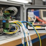
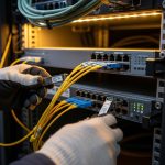
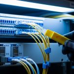
When a fiber transceiver goes flaky in a live network, the symptoms look deceptively simple: link flaps, CRC spikes, and sudden loss of traffic. This article gives field-ready troubleshooting steps for fiber module failures in critical operations, especially when you cannot afford downtime. It helps NOC engineers, data center field techs, and reliability teams isolate whether the issue is the optics, the module, the fiber path, or the switch port.
Field symptoms: fiber module vs port vs fiber path (what to compare)
Before you swap anything, capture evidence. In most production environments, the fastest path to root cause is correlating link state, interface counters, and optical power with the timing of the incident. IEEE 802.3 defines how link training and physical layer signaling behave, but vendors expose it differently via CLI and diagnostics. Your goal is to decide whether the failure behaves like a transceiver problem, a port problem, or an end-to-end fiber impairment.
Compare these indicators in the first 10 minutes
- Link flaps only on one port: suspect module aging, connector contamination, or a marginal splice.
- CRC and FCS errors rising without link down: suspect optical power budget issues, dirty connectors, or bad fiber alignment.
- Sudden total outage after a maintenance window: suspect wrong fiber patching, polarization mismatch (rare for multimode, common for certain single-mode scenarios), or a partially seated module.
- Temperature-related instability: some modules degrade under heat soak; check chassis airflow and adjacent module density.

Head-to-head: module swap, port swap, or fiber cleaning first?
In critical operations, the “right” troubleshooting steps depend on the failure signature and how quickly you can validate hypotheses. A clean, repeatable approach is to run a controlled A/B test: swap the minimum variable that can explain the observed counters. The comparison below frames three common options and when each is the fastest route to confirmation.
Decision comparison table (performance, cost, and time-to-root-cause)
| Option | Best for | Typical validation time | What you learn | Main risk |
|---|---|---|---|---|
| Swap the fiber module (known-good SFP/SFP+/QSFP) | Link flaps, high BER, CRC bursts, repeated LOS | 5-20 min | Whether optics/electronics in the module are failing | Compatibility mismatch (wrong vendor or wrong DOM) |
| Swap the switch port (known-good port or module on another port) | Port-specific behavior, consistent errors after module is confirmed OK | 10-30 min | Whether the PHY/laser biasing on the port is unstable | May disrupt other traffic if you have to move too much |
| Clean and re-terminate connectors / re-check patching | CRC/FCS errors without link down, intermittent link, incident after touch/patch changes | 15-45 min | Whether contamination or connector geometry is causing power loss | If you skip inspection, you can “fix” nothing |
Use optics diagnostics to decide which swap is most economical
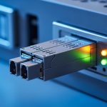
Most modern transceivers expose DOM (Digital Optical Monitoring) values such as laser bias current, transmit power, receive power, and module temperature. Compare current readings to historical baselines if you have them. If receive power is low for an otherwise stable module, connector contamination or fiber attenuation is more likely than a defective switch port. If the module’s transmit power is unstable or laser bias is trending unusually, the module is a prime suspect.
Pro Tip: If a module’s DOM temperature is normal but its transmit power is drifting over minutes, suspect a marginal solder joint or aging laser driver inside the transceiver. In field cases, cleaning connectors fixes CRC errors but does not stop transmit power drift—DOM trend graphs reveal that difference faster than waiting for another full outage.
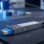
Specs that matter: wavelength, reach, power, and temperature limits
Compatibility failures are a classic root cause of “module failure” reports. Even when the module physically fits, mismatched standard types (10G SR vs 10G LR vs 100G SR4), wrong wavelength, or out-of-range optics can cause link loss or degraded BER. IEEE 802.3 and vendor datasheets define optical parameters, but your switch vendor’s supported optics matrix often adds extra constraints like DOM polling behavior and vendor-specific calibration.
Quick reference: common fiber module types and constraints
Use this table to sanity-check the basics before deeper diagnostics. Exact values vary by vendor, but these ranges are representative for planning troubleshooting steps.
| Module type | Typical wavelength | Connector | Reach (typical) | Optical power monitoring | Operating temperature | Common failure signature |
|---|---|---|---|---|---|---|
| SFP-10G-SR (multimode) | 850 nm | LC | Up to 300 m (OM3/OM4 planning dependent) | DOM Tx/Rx power, bias current | About 0 to 70 C (commercial) or -40 to 85 C (extended) | LOS after patching, BER spikes with dirty connectors |
| SFP+-10G-LR (single-mode) | 1310 nm | LC | Up to 10 km (single-mode planning dependent) | DOM Tx/Rx power, bias current | Similar ranges by grade | Low Rx power due to fiber attenuation or wrong patch |
| QSFP28-100G-SR4 | 850 nm | MPO/MTP (4 lanes) | Up to 100 m common for OM4 planning | DOM per-lane is common | Lane imbalance, link down due to MPO polarity or dust |
Real-world compatibility caveat: DOM and lane mapping
In one deployment, we replaced 100G QSFP28 SR4 modules with third-party equivalents to reduce cost. The link trained but intermittently dropped under load because the switch expected a specific DOM behavior and the MPO polarity mapping was effectively reversed for two lanes. The fix was not “better optics,” it was ensuring the module was in the switch’s supported optics list and verifying MPO polarity with a proper polarity tester. For evidence, see vendor compatibility guidance and general DOM behavior discussions in [Source: Cisco QSFP and SFP documentation] and [Source: IEEE 802.3 physical layer overview].
anchor-text: IEEE 802.3 physical layer
anchor-text: Vendor transceiver and DOM compatibility guidance

Troubleshooting steps: a practical workflow that reduces downtime
Here is a field workflow you can run while keeping the incident under control. The emphasis is on fast hypothesis testing, careful measurements, and avoiding “shotgun swapping” that wastes spares. The goal is to produce a root-cause conclusion you can document for ISO 9001 style traceability and reliability reporting (including MTBF impacts).
Freeze the state and record counters
Document the exact interface identifiers, time of first alert, and the counter deltas. Capture link state changes, CRC/FCS, symbol errors if available, and any LOS/LOF alarms. If your switch supports it, export optical diagnostics (DOM) readings at incident start and again after 5 to 10 minutes. This makes your later comparisons defensible.
Validate module identity and standard type
Confirm the module’s part number and that it matches the expected standard for the port (for example, SR vs LR, and SR4 lane count). Check whether the module is rated for the environment grade (commercial vs industrial/extended). If you are using third-party optics, confirm the switch is configured for optics compatibility and that the module is in the vendor’s supported list where applicable.
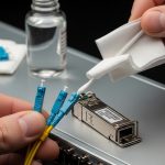
Inspect connectors with magnification, then clean correctly
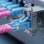
Connector contamination is one of the most common causes of intermittent failures. Use an inspection scope to look for scratches, residue, or haze on the fiber endface. Clean with the correct method for your connector type (LC vs MPO/MTP) and verify again with inspection. If you skip inspection and only “clean blindly,” you can waste time and still have low Rx power.
Check patching and polarity end-to-end
For multimode SR and especially for SR4 with MPO, verify that the transmit fibers connect to receive fibers correctly. Use a polarity map and label the fibers before you move anything. A wrong patch can produce low receive power or high lane imbalance, which looks like a failing module even when the optics are healthy.
Compare DOM Tx/Rx power to expected budgets
Use the vendor’s optical budget guidance and your link distance/patch loss assumptions. If DOM receive power is consistently near the low end of the module’s sensitivity, minor contamination or patch loss changes can trigger LOS. If Tx bias current is elevated while output power is unstable, the module may be degrading.
Controlled swap tests (module-first vs port-first)
Now choose the minimal swap. If you suspect the module, move a known-good module into the same port. If the symptoms follow the module, you likely found the failing unit. If the symptoms follow the port, suspect a PHY/port issue or a marginal cage seating problem.
Pro Tip: For QSFP28 SR4 and other multi-lane optics, a “works sometimes” issue is often lane imbalance from MPO polarity or uneven fiber damage. Swapping the entire module can mask the symptom, so always inspect MPO endfaces and verify polarity before you conclude the transceiver is bad.

Common mistakes and troubleshooting tips that prevent repeat failures
Even experienced teams fall into predictable traps. These are the failure modes we see most often, along with root cause and a fix you can apply immediately.
Cleaning without inspection (root cause: contamination remains)
What happens: You clean connectors, but the link still flaps or CRC errors persist. Root cause: Residue or micro-scratches remain, or you cleaned the wrong connector end. Solution: Inspect before and after cleaning using a scope; if you see scratches, replace the patch cord or re-terminate.
Swapping optics that are “compatible,” but not actually supported
What happens: Link comes up briefly, then drops under temperature or load. Root cause: DOM behavior or calibration differences, plus switch optics compatibility filters. Solution: Verify supported optics lists, confirm correct standard (SR vs LR), and validate DOM stability over 10 to 15 minutes under normal load.
Ignoring MPO polarity and lane mapping for multi-lane modules
What happens: 100G SR4 links show high errors, partial lane failures, or intermittent drops. Root cause: Transmit/receive lane polarity mismatch or damaged ribbon fibers inside the MPO. Solution: Use a polarity tester and confirm lane mapping; replace suspect MPO jumpers and re-check with endface inspection.
Treating low Rx power as “just a bad module”
What happens: You replace transceivers repeatedly, but receive power stays marginal. Root cause: Patch loss, dirty adapters, broken fibers, or wrong fiber type (for example, using OM3-grade cabling where OM4 is required for a planned reach). Solution: Measure end-to-end loss when possible, inspect adapters, and verify fiber grade and patching.
Cost and ROI note: OEM vs third-party optics in critical networks
Costs vary widely by speed and reach, but you can plan realistic ranges. In many North American enterprise and colocation environments, third-party SFP+ modules might cost roughly $25 to $80, while OEM equivalents can be $80 to $250 depending on vendor and grade. For QSFP28 100G optics, third-party pricing might be $200 to $600 versus OEM often $500 to $1,500. The ROI question is not only purchase price: it is spares stocking, failure rates, and time-to-repair.
For reliability planning, track failure events per module type and compute MTBF trends internally. If third-party optics show higher early-failure rates (burn-in issues or connector handling differences), your TCO can rise due to more RMA cycles and longer maintenance windows. In critical operations, the cost of one extended outage typically dwarfs the optics delta, so prioritize proven compatibility with your switch platform and documented optical budgets.
Selection guide: decision checklist for troubleshooting and replacement
Use this ordered checklist during troubleshooting steps so decisions stay consistent across shifts and tickets. It also supports auditability for quality management systems.
- Distance and reach match: Confirm your planned reach vs actual fiber type and measured patch loss.
- Standard and wavelength match: Verify SR vs LR vs SR4 and correct wavelength (850 nm vs 1310 nm vs 1550 nm).
- Switch compatibility: Check the vendor’s supported optics list and validate DOM polling behavior.
- DOM support and alarm behavior: Ensure the module exposes Tx/Rx power and that alarms map correctly in your monitoring system.
- Operating temperature and airflow: Verify chassis airflow; check module temperature trends during the incident.
- Connector and patch hygiene: Use inspection scopes and correct cleaning tools; verify MPO polarity for multi-lane optics.
- Vendor lock-in risk: If you plan third-party optics, require compatibility testing in a staging rack before rolling out.
Decision matrix: choose the fastest troubleshooting path
The matrix below helps you pick which head-to-head option to start with based on what you see first. It is designed for speed and confidence rather than perfect theory.
| Observed behavior | Most likely root cause | Start with | Confirm with |
|---|---|---|---|
| Link down with LOS | Low optical power, module failure, or severe fiber issue | Swap module | DOM Rx power and inspection of connectors |
| CRC/FCS errors climbing, link stays up | Dirty connectors, marginal optical budget, fiber damage | Inspect and clean connectors | Re-check Rx power stability and error counters |
| Intermittent drops after patch changes | Patching error or MPO polarity mismatch | Verify patching and polarity | Polarity tester results and scope inspection |
| Errors follow the port after module swap | Port PHY, cage seating, or hardware issue | Swap port | Compare behavior with known-good module |
| Instability correlated with heat | Thermal stress, airflow issues, or failing module driver | Check temperature and airflow | DOM temperature and bias current trend |
Which Option Should You Choose?
If you are chasing fast confirmation during an outage, choose module swap first for LOS/link-down patterns and connector inspection plus cleaning first for CRC-heavy patterns where the link stays up. If your environment uses multi-lane optics like QSFP28 SR4, start with MPO polarity verification and endface inspection because lane mapping mistakes are disproportionately common. For teams optimizing cost without sacrificing reliability, pilot third-party optics only after compatibility testing against your specific switch model and monitoring stack.
If you tell me your switch model, transceiver part numbers, and the exact alert text (LOS, LOF, CRC, symbol errors), I can help you turn these troubleshooting steps into a tighter runbook for your site. Meanwhile, you can cross-check your fiber health workflow with fiber patch cord cleaning and testing to reduce repeat incidents.
FAQ
What are the first troubleshooting steps when a fiber link flaps?
Start by recording interface counters and DOM values at the moment the flap occurs. Then inspect connectors with a scope and confirm the module type matches the port standard. If the symptom follows the module after a swap, you are likely dealing with a failing transceiver or its optics.
How do I tell if the module is bad versus the switch port?
Use a controlled swap: move the known-good module into the suspected port, and then move the suspected module into a known-good port. If the failure follows the module, it is the transceiver; if it follows the port, it points to the PHY/cage or a hardware seating issue.
Why do I see CRC errors without link down?
CRC/FCS errors usually indicate a marginal optical path or contamination rather than a complete loss of signal. Dirty connectors, patch loss, or slight misalignment often produce this signature. Inspect, clean, and then verify Rx power stability against the vendor’s optical budget guidance.
Can third-party optics cause intermittent failures?
Yes, especially if the module is not fully compatible with your switch’s optics support and DOM expectations. Some optics may train but behave poorly under temperature changes or during monitoring polling. The safest approach is compatibility testing in a staging rack before production rollout.
What should I check for QSFP28 SR4 or other MPO-based links?
Verify MPO/MTP polarity with a tester and inspect each endface for dust or scratches. Lane imbalance can look like a “bad module,” but the root cause is often incorrect polarity or damaged ribbon fibers. After corrections, re-check per-lane DOM values if your switch exposes them.
How can we avoid repeat transceiver failures and improve MTBF?
Track failures by module type and by connector/patch location, then correlate events with cleaning and maintenance logs. Implement a scope-inspection-first policy and require polarity verification for MPO jumpers. Over time, this reduces early failures and improves your internal MTBF metrics.
Author bio: I work as a reliability-focused field engineer, building repeatable troubleshooting steps for fiber networks in live data centers. I also help teams quantify optics risk using DOM trend analysis, connector hygiene controls, and MTBF-informed maintenance planning.
Next step: Strengthen your runbook by reviewing fiber patch cord cleaning and testing so your team can prevent contamination-driven outages before they start.