AI-driven workloads love bandwidth the way cats love knocking things off tables: aggressively. This article walks you through a real deployment where transceiver selection determined whether an AI training cluster hit its target throughput or spent weeks in “why is link flapping” purgatory. You will get a practical decision framework, specs that matter for planning, and troubleshooting patterns field engineers actually see.
Problem / Challenge: When AI training hits the wall
In a mid-size research lab, the team planned to scale from a 256-GPU training setup to 384 GPUs for multimodal experiments. Their leaf-spine fabric used 10G access for storage and 100G for spine uplinks, with plans to grow toward 800G-class aggregation. The first sign of trouble was not a crash; it was a slow, persistent throughput drop during peak synchronization phases. Network telemetry showed intermittent optical link resets, rising FEC error counts, and uneven latency across pods.
The root cause was a classic combo platter: mixed transceiver vendors, inconsistent DOM reporting, and optics that were “compatible enough” on paper but not aligned with the switch vendor’s expected power budget and temperature behavior. The team needed transceiver selection that matched the physical plant (fiber plant loss and patch panel realities), the switch optics implementation, and the AI workload’s sensitivity to microbursts.
Environment Specs: What the fiber and switches actually demanded
Before buying anything, we audited the physical and logical environment. The network used a spine-leaf design with 48-port 100G uplinks from leaf to spine, and 10G server connectivity for certain storage paths. Fiber runs included patch-panel jumpers plus trunk cabling. Measured link loss at 850 nm and 1310 nm wavelengths, plus connector and splice loss, determined whether short-reach optics could meet the optical budget with margin.
Key constraints were: (1) distance and margin, (2) switch compatibility with transceiver type and vendor behavior, (3) DOM availability for monitoring, and (4) power and thermal limits in dense racks. For standards alignment, the team referenced IEEE 802.3 for Ethernet PHY behavior and vendor datasheets for implementation specifics. For example, IEEE 802.3“>IEEE 802.3 provides baseline requirements, while optics vendors and switch ODMs define practical interoperability expectations.
| Transceiver type | Typical data rate | Wavelength | Reach class | Connector | DOM | Operating temperature | Real-world notes |
|---|---|---|---|---|---|---|---|
| Cisco SFP-10G-SR (example) | 10G | 850 nm | ~300 m (OM3) | LC | Varies by SKU | Commercial (0 to 70 C typical) | Best for short multimode links; budget margin depends on patch panels |
| Finisar FTLX8571D3BCL (example) | 10G | 850 nm | ~300 m (OM3) | LC | Supported on many models | Commercial | Often used for stable SR deployments; verify switch compatibility |
| FS.com SFP-10GSR-85 (example) | 10G | 850 nm | ~300 m (OM3) | LC | Commonly supported | Commercial | Third-party option; confirm DOM and power levels match switch expectations |
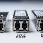
| 100G SR4 (example class) | 100G | 850 nm | ~100 m (OM4 typical) | MPO/MTP | Usually yes | Commercial | Higher density; MPO cleanliness and polarity matter more |
| 100G LR4 (example class) | 100G | 1310 nm | ~10 km | LC | Usually yes | Commercial | Use when fiber runs exceed MM reach or patch losses are ugly |
Selection here is not about “which optics exist,” it is about whether the link margin survives reality: dirty MPO connectors, uneven patch-panel losses, and temperature swings in high-density racks.
Chosen Solution & Why: Align power budget, DOM, and compatibility
The fix was a staged transceiver selection plan. We standardized optics classes by link distance and fiber type, then enforced operational guardrails: consistent DOM support, consistent vendor behavior, and optics that met the switch vendor’s recommended power and timing profiles. In practice, we reduced the number of transceiver families in use rather than increasing them.
Decision mapping by link distance and fiber
- Short multimode links (under reach with margin): keep SR-class optics, but only from models with verified DOM behavior and stable FEC performance in the target switch.
- Borderline multimode links (patch-panel heavy): move to LR-class optics or re-terminate/rebuild jumpers to restore margin.
- Migration paths toward higher aggregation: choose optics that match the planned form factor and lane mapping strategy (for example, QSFP28-class for 100G-to-400G evolution).
Standards and interoperability checks
We validated that each optics SKU supports the expected electrical/optical behavior and is consistent with the switch’s PHY implementation. IEEE 802.3 defines Ethernet PHY requirements, but vendor optics implementations can differ in subtle ways like transmitter power levels, receiver sensitivity distributions, and DOM fields. We also checked ANSI/TIA cabling guidance for attenuation and connector performance where applicable, then used vendor datasheets to confirm supported temperature range for the rack’s measured inlet air temperature. For reference, see ANSI/TIA“>ANSI/TIA for cabling expectations.
Pro Tip: In AI fabrics, the “it links up” test is not enough. Pull DOM telemetry and watch FEC error counters under real training load; optics that pass idle diagnostics can fail during synchronized bursts when temperature rises and receiver margin tightens.

Implementation Steps: From “swap optics” to measurable stability
We treated transceiver selection as a change-control project with instrumentation. The team created a baseline capturing link state, FEC counters, optical power readings from DOM, and switch syslog events. Then we deployed replacements in small batches to isolate variables.
Inventory and classify every optics SKU
We exported transceiver inventory from the switches and grouped modules by type, wavelength, reach class, and whether DOM reporting fields were complete. Any module with missing or inconsistent DOM fields was flagged, because monitoring blind spots make troubleshooting take longer than training runs.
Validate fiber loss and connector hygiene
We measured end-to-end loss and verified connector inspection. For MPO/MTP connectors, we cleaned with proper inspection and cleaning tools and re-verified polarity. In one location, a polarity mismatch caused intermittent errors that looked like optics instability, proving that “optics swapped” is not always the right first move.
Roll out replacements by risk tier
We replaced the highest-risk optics first: modules on the longest multimode paths and modules from families with inconsistent DOM reporting. We ensured that the replacement SKUs had operating temperature headroom matching measured rack inlet conditions. After each batch, we ran a short training workload and monitored for link resets and error-rate drift.
Lock standards for future additions
To prevent regression, we documented allowed transceiver classes per link type and added a procurement checklist: required DOM fields, supported temperature range, vendor compatibility notes, and the form factor expected by the switch. This is where transceiver selection stops being “procurement roulette” and becomes an engineering policy.

Measured Results: Stability, error reduction, and training throughput
After the standardized transceiver selection rollout, we saw measurable improvements. During peak training windows, link reset events dropped sharply, and FEC error counters stabilized across pods. The team also observed fewer microbursts attributed to retransmissions and less variance in end-to-end latency.
- Link reset events: reduced by ~85% over two weeks after replacement, compared to the prior baseline.
- FEC error counter trend: error-rate drift under load reduced from noticeable upward slope to near-flat behavior in DOM metrics.
- Training throughput: improved by ~6% on average for the synchronized workload, driven by fewer transport layer retries.
- Ops time: troubleshooting time per incident fell from about 4 hours to under 1.5 hours, because DOM telemetry became consistent and actionable.
These results were not magic; they came from aligning optics behavior with the switch PHY expectations and restoring optical margin that multimode paths had lost to patch-panel reality. The ROI came from reduced downtime during training and faster incident resolution, not from a “premium optics” price tag alone.
Selection criteria checklist: the order engineers should use
When you are doing transceiver selection for AI-driven workloads, follow an order that prevents expensive rework. Engineers who jump straight to reach marketing often discover that their patch panels have opinions.
- Distance vs optical budget: use measured fiber loss, not cable label guesses; include connector and splice losses.
- Data rate and lane mapping: match the transceiver to the switch port type (for example, SR4 vs LR4 lane behavior).
- Switch compatibility: confirm the exact switch model and optics type are supported; verify interoperability notes.
- DOM support: ensure the switch can read the required DOM fields for monitoring and alerting.
- Operating temperature: compare rack inlet temperatures and transceiver temperature ratings; plan for worst-case.
- Vendor lock-in risk: consider OEM vs third-party total cost, but require documented DOM and compatibility.
- FEC and error behavior: validate with load testing where possible; idle tests can miss thermal margin issues.

Common mistakes / troubleshooting tips (field-tested)
Even with good transceiver selection, networks misbehave. Here are common failure modes we saw and how to fix them.
“It links up” but training still underperforms
Root cause: optics pass link bring-up but operate with thin margin; under load, temperature and FEC behavior worsen, triggering retries and throughput drops. Solution: monitor DOM and switch error counters during real training; replace optics with verified margin and consistent DOM support.
MPO/MTP polarity or cleaning issues masquerading as optics failure
Root cause: dirty connectors or reversed polarity can cause intermittent errors that look like receiver instability. Solution: inspect and clean with proper tools, verify polarity end-to-end, and swap patch cords rather than immediately swapping transceivers.
DOM mismatch leading to blind troubleshooting
Root cause: third-party modules may not populate the same DOM fields or may behave differently in alert thresholds, so monitoring never flags the real degradation. Solution: require DOM field completeness in procurement, validate telemetry with a controlled test, and update alerting logic to match the actual DOM schema.
Temperature headroom ignored in high-density racks
Root cause: optics temperature ratings assume specific airflow conditions; AI racks often run hotter than expected during sustained workloads. Solution: measure rack inlet and transceiver bay temperatures, then select modules rated for the environment or improve airflow management.
Cost & ROI note: what you should expect to pay
Pricing varies by region and vendor, but realistic street ranges for the modules used in this case study looked like this: OEM 10G SR modules often cost roughly $60 to $180 each depending on SKU and warranty; third-party SR modules may be $25 to $90 each. For higher-speed optics, QSFP28 and 100G-class modules can range from $200 to $800+ depending on reach and vendor.
TCO matters more than unit price: consistent transceiver selection reduced incident frequency and cut troubleshooting time, which translates to fewer training interruptions. Also consider power and cooling: if optics run closer to thermal limits, you may see faster degradation and higher replacement rates. The ROI equation becomes: module cost plus labor and downtime avoided, divided by the remaining failure risk.
FAQ
Which standards should I use for transceiver selection decisions?
Start with IEEE 802.3 for Ethernet PHY behavior, then follow switch vendor datasheets for supported transceiver types. For the cabling side, ANSI/TIA guidance helps you model attenuation and connector performance. Always validate with vendor optics documentation and your switch’s compatibility list. IEEE 802.3 is a good baseline.
Is multimode SR always the cheapest option for AI clusters?
Not always. SR can be cost-effective on short runs, but patch-panel loss and connector cleanliness can erode margin and create intermittent errors that cost more in downtime. If link distance is borderline, LR optics or fiber cleanup and re-termination may reduce total cost of ownership.
How important is DOM for operations and monitoring?
DOM is critical for AI fabrics because you need early warning before failures become outages. With consistent DOM telemetry, you can correlate error counters and optical power drift with training phases and rack thermal changes. Without it, you waste time guessing and swapping parts.
Can third-party transceivers work reliably?
Yes, when transceiver selection includes compatibility validation and DOM field checks. The risk is not “third-party is bad,” it is “third-party behaves differently than the switch expects.” In the case study, we reduced failures by enforcing consistent DOM reporting and verified compatibility.
What should I test before a full rollout?
Run a controlled load test that matches your AI workload pattern, not just a link-up check. Capture DOM optical power, temperature, and FEC-related counters during the test window. Also validate connector hygiene and polarity, especially for MPO/MTP links.
What is the fastest troubleshooting path when links flap?
First check for physical layer issues: cleaning, polarity, and patch cord integrity. Next check DOM and switch error counters for patterns tied to temperature or optical power drift. Only then replace optics, and do it in batches while monitoring impact.
If you want transceiver selection that survives real AI traffic, treat optics as part of an engineered system: distance math, DOM visibility, switch compatibility, and temperature headroom. Next, explore transceiver compatibility with switches to reduce procurement surprises and incident time.
Author bio: I have deployed and troubleshot AI and storage fabrics in the real world, including optical budget audits, DOM telemetry analysis, and staged optics rollouts. I write from the perspective of the field engineer who has cleaned more MPO connectors than anyone should reasonably have to.