In many enterprises, the first sign of a failing optics fleet is not a warning log, but a link flapping event during peak hours. This article helps network, data center, and field operations teams build repeatable processes for transceiver lifecycle management, reducing unplanned downtime while controlling total cost of ownership. You will get practical selection criteria, a troubleshooting playbook, and deployment examples grounded in real switch and optical module constraints.
Why transceiver lifecycle management fails in real networks
Most optic problems are predictable, but teams often treat transceivers as “install and forget” hardware. In practice, transceivers age through thermal cycling, connector wear, fiber contamination, and vendor-specific implementation details that only show up under load. IEEE 802.3 defines electrical and optical behavior at the protocol layer, but it does not guarantee that every vendor’s DOM reporting, laser bias control, or compliance margin will behave identically across temperature and link partners. The result is lifecycle drift: inventory, firmware expectations, and physical plant conditions diverge over time.
Think of a transceiver like a car tire in a fleet: the tread depth matters, the alignment matters, and the road conditions matter. If you only count miles and never check pressure or rotation, you will eventually see blowouts. Similarly, if you only track “quantity installed” and never monitor DOM trends, you will eventually see intermittent errors, high BER, or unexpected link drops.
Core lifecycle stages: from procurement to end-of-life
A reliable transceiver lifecycle program is a pipeline with gates. Each gate has measurable inputs—DOM thresholds, port error counters, temperature exposure history, and compatibility constraints—so you can authorize reuse, planned replacement, or retirement. The goal is to prevent “unknown inventory” and “unknown optics health” from becoming operational risk.
Stage 1: Procurement and qualification gates
Start by standardizing part numbers and optics families per speed and medium: for example, 10G SR (850 nm multimode), 10G LR (1310 nm single-mode), or 25G/100G variants. In the field, a common mistake is mixing “functionally similar” optics from different vendors without validating compatibility. Many enterprise switches enforce deterministic behavior around EEPROM contents, DOM parsing, and digital diagnostics. Use vendor datasheets and switch transceiver compatibility matrices as your authoritative baseline, and validate with a lab run before broad rollout.
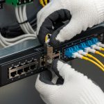
Stage 2: Installation controls and physical plant hygiene
Connector contamination is a leading root cause of intermittent link events. Build a standard: clean fiber ends with lint-free wipes and approved cleaning tools, inspect with a microscope or fiber inspection scope, and document cleaning results for high-value links. Record which patch panels, jumpers, and transceiver serials were paired. This is not bureaucracy; it is traceability that speeds incident response.
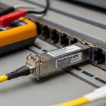
Stage 3: Monitoring with DOM and error counters
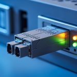
Digital Optical Monitoring (DOM) typically reports parameters such as laser bias current, received signal power (Rx power), transmit power, and module temperature. Your monitoring system should correlate DOM trends with interface counters like CRC errors, symbol errors, and link flaps. The lifecycle insight comes from trend lines: a module that slowly degrades will show increasing temperature, shifting Rx power, or changing bias current long before it fully fails.
Reference point: IEEE 802.3 establishes link behavior and optical/electrical requirements for Ethernet PHYs. For optical diagnostics, consult vendor documentation for DOM register mapping and thresholds (for example, SFF-8472 for legacy transceivers and SFF-8431/8432 families for newer digital diagnostics). IEEE 802.3 standard provides the protocol and PHY requirements context. SNIA is useful for broader storage and infrastructure reliability practices, including operational hygiene concepts.
Stage 4: Planned refresh and end-of-life retirement
Define a refresh cadence based on environmental stress and observed failure rates. For example, in high-density racks with frequent airflow changes, you may refresh earlier than in stable telecom rooms. When a module crosses your DOM degradation threshold or shows repeated error bursts, move it into a quarantine pool for inspection and controlled replacement. End-of-life retirement should also cover inventory accuracy—ensure the retirement event updates your asset database, so “available spares” do not become phantom stock.
Pro Tip: In field deployments, the most actionable lifecycle signal is not a single DOM reading; it is the slope. A transceiver whose Rx power decreases by a few tenths of a dB over months while temperature rises is often a contamination or aging precursor, even if the link is still “up.” Logging trends weekly lets you replace before you cross the link budget margin and start seeing intermittent CRCs.

Technical specifications that drive lifecycle decisions
Different transceiver types have different optical budgets, thermal sensitivities, and connector interfaces. Lifecycle planning must align to speed class, medium type, and connector standard, because those factors determine how aggressively you need to monitor and how soon you should rotate spares.
| Transceiver type example | Typical wavelength | Reach class | Connector / medium | Data rate | DOM visibility | Operating temp (typ.) |
|---|---|---|---|---|---|---|
| SFP-10G-SR (850 nm) | 850 nm | Up to 300 m OM3 / 400-550 m OM4 (varies) | LC, multimode fiber | 10G | Bias current, Tx/Rx power, temp | 0 to 70 C (commercial) or wider for extended |
| QSFP28-100G-SR4 (850 nm) | 850 nm | Up to 100 m typical for SR4 OM4 (depends on vendor) | LC, multimode fiber | 100G (4 lanes) | Per-lane diagnostics | 0 to 70 C (commercial) or wider |
| QSFP28-100G-LR4 (1310 nm) | 1310 nm | Up to 10 km (varies by spec) | LC, single-mode fiber | 100G (4 lanes) | Digital diagnostics | -5 to 85 C (varies by product) |
When selecting modules, verify the exact part number and compatibility with your switch model. For instance, Cisco optics are often validated with Cisco switch platforms such as Cisco Nexus and Catalyst families, while third-party optics may require specific firmware compatibility and may report DOM values differently. As examples of commonly referenced optics SKUs: Cisco SFP-10G-SR, Finisar FTLX8571D3BCL, and FS.com SFP-10GSR-85. Always consult the vendor datasheet for your exact temperature grade and DOM behavior.
Cost and availability also vary by wavelength and reach class. SR modules are typically cheaper per port than LR optics, but they are more sensitive to multimode patching quality and connector cleanliness. LR modules shift the burden toward single-mode plant quality and link budget margin stability.
Deployment scenario: leaf-spine data center with staged refresh
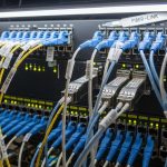
Consider a 3-tier data center leaf-spine topology with 48-port 10G ToR switches and 100G uplinks. The environment runs 24-hour peak traffic, with typical optics types: SFP-10G-SR to servers and QSFP28-100G-LR4 on spine uplinks. The team manages 2,400 server-facing 10G ports and 192 spine uplink ports, totaling around 2,592 active transceivers. They deploy a lifecycle refresh policy where new optics are installed in “green” racks first, then rolled out to “amber” racks after compatibility validation.
Operationally, they monitor DOM parameters and interface counters every 15 minutes using a collector that ingests Tx bias, Rx power, module temperature, and port CRC/symbol error counters. After six months, they see a pattern: modules in one patch panel show decreasing Rx power by about 0.2 dB per month, correlated with repeated cleaning events and a high number of technician reconnects. Rather than waiting for failures, they schedule a planned replacement of the affected patch set and transceivers during a maintenance window, reducing link flaps during peak hours. This is lifecycle management as risk reduction, not as reactive firefighting.
Selection criteria checklist for transceiver lifecycle programs
Engineers usually need a structured decision process so procurement, operations, and incident response all align. Use the ordered checklist below as a repeatable gate for each transceiver family and vendor.
- Distance and link budget: Confirm reach class against your fiber type (OM3/OM4 for SR, OS2 for LR), patch loss, and expected aging margin.
- Switch compatibility: Validate with your exact switch model and software release; confirm DOM parsing behavior and any vendor lock constraints.
- DOM support and thresholding: Ensure the module reports consistent Tx/Rx power and temperature; define acceptable ranges and alert thresholds.
- Operating temperature and thermal cycling: Choose commercial vs extended temperature grades based on rack airflow and ambient variability.
- Connector and cleaning ecosystem: Verify connector type (LC vs MTP/MPO), polarity handling, and cleaning tool availability for your team.
- Inventory strategy and spares policy: Decide whether spares are “like-for-like” or if cross-compatible optics are allowed with documented validation.
- Vendor lock-in risk: Track which vendors provide reliable DOM behavior and documentation; include fallback options to avoid supply shocks.
OEM vs third-party considerations
OEM optics can reduce compatibility surprises, but they may carry higher per-unit cost and longer lead times. Third-party optics can be cost-effective, but they require stronger validation: DOM register mapping, compliance with the relevant SFF standards, and consistent behavior across temperature. In lifecycle terms, the “cheapest module” is often the one that minimizes total failures, avoids truck rolls, and maintains stable link performance.
Common mistakes and troubleshooting tips
Even with good processes, failures happen. The key is to recognize common failure modes quickly and apply the correct fix without damaging the physical plant or wasting time swapping parts blindly.
Mixing optics vendors without compatibility validation
Root cause: Different vendors may implement DOM reporting differently or have edge-case behavior around EEPROM contents and threshold defaults. Some switch platforms are tolerant; others are strict.
Solution: Maintain a compatibility matrix per switch model and software version. Run a lab validation with at least one module per vendor and monitor DOM and error counters for stability before scaling.
Ignoring DOM trends until the link fails
Root cause: Teams often alert only on link-down events, not on gradual drift in Rx power or rising laser bias current. By the time CRC errors spike, the transceiver may already be beyond a safe operating margin.
Solution: Alert on early warning thresholds such as Rx power drift rate, temperature excursions, and increasing error counters even while the link remains up.
Fiber contamination after “successful” cleaning
Root cause: Cleaning can appear successful visually, but microscopic residue or connector damage can still cause intermittent attenuation. Repeated insertions also wear connector ferrules.
Solution: Use an inspection scope before and after cleaning. Track which connectors are repeatedly opened; consider scheduled connector replacement on high-touch patch panels.
Incorrect polarity or MPO/MTP lane mapping
Root cause: On multi-fiber connectors, lane mapping errors can cause partial lane failures that manifest as high BER or intermittent drops.
Solution: Enforce polarity labeling standards, verify MPO/MTP cassettes, and document lane mapping per link type. Validate with a known-good transceiver set during troubleshooting.

Cost and ROI: budgeting the transceiver lifecycle
Enterprise optics budgets typically include module purchase cost, spares inventory, and operational cost from field replacement. As a practical range, many 10G SR modules may be in the tens of dollars to low hundreds per unit depending on OEM vs third-party, while 100G optics can be significantly higher. The ROI comes from reducing truck rolls, preventing downtime during peak windows, and improving first-time fix rates.
Third-party optics can reduce purchase price, but TCO depends on failure rates, validation effort, and whether your monitoring catches drift early. If your monitoring is weak, cheaper optics can increase incident frequency and labor costs. A well-run lifecycle program often improves mean time to repair (MTTR) because you can identify “at-risk” modules before they fail and you have accurate asset and replacement history.
FAQ
How do I set DOM thresholds for transceiver lifecycle alerts?
Start with vendor datasheet guidance and baseline your environment. Collect DOM readings for each module type for at least two to four weeks, then set thresholds for Rx power drift rate and temperature excursions. Use a staged alerting approach: warning first (trend-based), then critical (error counter and link stability confirmation).
Are SFP, SFP+, and QSFP optics interchangeable for the same ports?
No. Even when data rates seem close, the physical form factor, electrical interface, and lane mapping differ. You must match the switch port type and the expected PHY standard; otherwise you risk incompatibility and unstable link behavior. Confirm in the switch’s transceiver compatibility list.
What is the most common cause of intermittent link flaps?
Fiber contamination and connector issues are frequent culprits, especially after maintenance activities. Another common cause is optics vendor mismatch or marginal link budget due to patching and aging. DOM trend monitoring plus a fiber inspection workflow usually identifies the faster root cause.
Should we standardize on OEM optics or allow third-party modules?
Many enterprises allow third-party modules but only after formal qualification and ongoing monitoring. OEM can reduce compatibility risk, while third-party can lower unit cost. The best approach is risk-based: allow third-party for low-risk segments first, then expand based on observed stability and lifecycle metrics.
How often should transceivers be rotated or replaced proactively?
There is no single universal cadence because temperature exposure, connector wear, and patching practices vary. A practical method is to define rotation based on observed drift: for example, replace modules when DOM trends indicate you are approaching link budget limits or when error counters show sustained degradation.
What documentation should we keep for each transceiver lifecycle event?
Record module part number, serial number, installation date, switch model and port, fiber path identifiers, and DOM baselines at install time. Also log cleaning and inspection evidence when you replace connectors or patch cords. This traceability shortens troubleshooting and strengthens future procurement decisions.
With a gated process—procurement qualification, installation hygiene, DOM trend monitoring, and planned retirement—transceiver lifecycle becomes a controlled reliability program rather than an emergency response. Next, align your monitoring and inventory workflows by reviewing transceiver monitoring for how to design alerts around DOM and error counters.
Author bio: I have deployed and supported high-density Ethernet optics in enterprise data centers, focusing on DOM-driven monitoring, fiber inspection workflows, and operational runbooks. I write from field experience with switch compatibility validation and incident response metrics.