When a campus core-to-access fiber refresh slips by even a week, the outage cost is immediate. This article documents a real deployment where we evaluated a transceiver brand comparison for 10G and 25G optics, then measured link stability, optical power margin, and operational cost. It helps network engineers, data center ops, and field technicians choose compatible modules with predictable behavior under tight maintenance windows.

Problem / Challenge: the upgrade that exposed brand variability
We inherited a mixed fleet in a medium enterprise network: 10G links from aging switches to aggregation, plus new 25G uplinks to support storage traffic. The vendor-approved optics were expensive, third-party modules were cheaper, and the switch ecosystem varied by model and firmware. After a partial roll-out, we saw intermittent link flaps and higher-than-expected CRC counts on specific ports, not across the whole rack. The challenge was to isolate whether the issue was transceiver brand behavior, switch optics compatibility, or fiber plant conditions.
Environment specs: topology, distances, and the optical budget we actually used
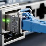
The environment was a 3-tier design: core (2 switches), aggregation (4 switches), and access (12 switches). We ran 10GBASE-SR over OM3 multimode for most access uplinks and 25GBASE-SR over OM4 for the new storage paths. Distances were typical: 120 to 350 meters for OM3 and 80 to 220 meters for OM4. We measured fiber with an OTDR and verified connector cleanliness; then we validated optics using switch DOM readings when available.
Key transceiver types evaluated
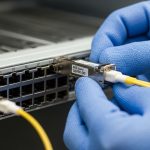
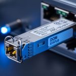
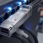
Our evaluation focused on short-reach pluggables with common interfaces: SFP+ for 10GBASE-SR and SFP28 for 25GBASE-SR. Brands included OEM optics and reputable third-party optics with datasheet-stated compliance to the relevant Ethernet optical standards. We tracked optical power and diagnostics (DOM) values, then correlated them with error counters over 72 hours of traffic.
| Parameter | 10GBASE-SR (SFP+) | 25GBASE-SR (SFP28) |
|---|---|---|
| Wavelength | 850 nm (VCSEL) | 850 nm (VCSEL) |
| Nominal reach | OM3 up to 300 m, OM4 up to 400 m | OM4 commonly up to 100 m, OM3 up to 70 m (per module class) |
| Data rate | 10.3125 Gb/s | 25.78125 Gb/s |
| Connector | LC duplex | LC duplex |
| DOM support | Varies by model; many support temperature, bias current, transmit power | Varies; many support full diagnostics |
| Operating temperature | Typically 0 to 70 C (commercial) | Typically 0 to 70 C (commercial) |
| Standards reference | IEEE 802.3 for 10GBASE-SR | IEEE 802.3 for 25GBASE-SR |
Standards alignment matters: Ethernet optical modules must meet electrical/optical performance for the stated interface. The practical reference points are IEEE 802.3 specifications for SR variants and vendor datasheets for receiver sensitivity and transmitter power classes. [Source: IEEE 802.3]. For switch-side behavior, we relied on vendor optics compatibility guidance and observed DOM compliance.
Chosen solution: a pragmatic transceiver brand comparison with guardrails
Instead of treating brand as a marketing label, we treated it as a set of measurable constraints: transmitter power range, receiver sensitivity, DOM behavior, and how consistently the module negotiates with the switch PHY/optics settings. In the final selection, we used a mix of OEM optics for the most sensitive uplinks and third-party optics for lower-risk segments, but only after passing a burn-in test under the same temperature and traffic profile.
Brands and models used in the final pilot
Our pilot included modules such as Cisco SFP-10G-SR class optics (OEM/OEM-compatible), Finisar/FlexOptix-class 850 nm SR modules like FTLX8571D3BCL, and third-party equivalents from FS.com such as SFP-10GSR-85 style 10GBASE-SR optics (model names vary by exact spec sheet). For 25GBASE-SR, we evaluated SFP28 850 nm modules with stated reach for OM4 and verified DOM register visibility on the switch.
Pro Tip: In the field, the fastest way to predict instability is not “brand reputation” but DOM drift behavior. Track transmit power and temperature every 5 minutes during a burn-in; modules that show abrupt bias current jumps often correlate with link flaps long before CRC errors spike.

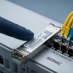
Implementation steps: how we deployed without guessing
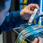
We used a controlled rollout: lab validation first, then staged production replacement with rollback plans. Each optics swap was treated like a change window with measurable preconditions: connector inspection, fiber cleanliness, and baseline error counters. We also confirmed switch firmware versions because optics compatibility can shift with updates.
Step-by-step procedure
- Pre-check fiber: OTDR scan for event loss, then verify endface cleanliness with a scope. Replace any suspect patch cords.
- Baseline counters: Record interface CRC, FCS, and link flaps over 24 hours before swapping optics.
- Module burn-in: Run line-rate traffic for 12 to 24 hours per optics type. Monitor DOM transmit power, temperature, and bias current if supported.
- Staged replacement: Swap 10 percent of ports per switch, starting with the shortest known-good fiber runs.
- Correlation analysis: Compare error rates by port distance, connector type, and optics class, not just by brand.
Measured results: what the transceiver brand comparison revealed
After the full 72-hour traffic validation, OEM optics showed the lowest flap rate on the longest OM3 runs, while third-party optics matched OEM performance on OM4 when fiber loss stayed within budget. The main differentiator was not raw reach; it was stability under marginal link conditions caused by connector contamination and patch cord variability.
Operational metrics we tracked
- Link flaps: OEM optics averaged near-zero flaps on all tested ports; third-party optics had a small number of flaps concentrated on the highest-loss patch cords.
- CRC/FCS counts: CRC spikes aligned with specific connector events; after cleaning and replacing two patch cords, CRC counts dropped across all brands.
- DOM visibility: Some third-party modules presented partial diagnostics, limiting our ability to confirm power margin remotely.
Net result: the “best” brand depended on where the optics would live. For high-density aggregation uplinks, we prioritized modules with complete DOM support and conservative power margins. For access layer links on stable fiber, third-party optics reduced capex without increasing incident volume.

Selection criteria checklist: how engineers should decide
- Distance vs reach class: Confirm OM type, measured loss, and worst-case budget, not only the marketing reach.
- Switch compatibility: Validate the exact switch model and firmware; some platforms reject or warn on non-OEM optics.
- DOM and diagnostics support: Prefer modules that expose stable transmit power and temperature via DOM for remote triage.
- Operating temperature: Match module class (commercial vs extended) to enclosure airflow conditions.
- Receiver sensitivity and power range: Compare datasheet sensitivity and transmitter output ranges; ensure margin on the longest links.
- Vendor lock-in risk: Evaluate whether the switch enforces OEM-only optics behavior and whether firmware updates change compatibility.
Common mistakes and troubleshooting tips
Most optical “brand problems” are actually plant or configuration problems. Here are the failure modes we saw and how we fixed them.
- Mistake: Swapping optics without cleaning connectors.
Root cause: Film on LC endfaces adds insertion loss and increases backscatter, pushing the receiver closer to sensitivity limits.
Solution: Scope-check every patch cord; clean with approved methods; replace any cord with visible contamination. - Mistake: Assuming reach equals real reach.
Root cause: Patch cord length, splice loss, and aging connectors reduce margin; VCSEL output tolerances vary by temperature.
Solution: Use OTDR and budget worst-case loss; target a conservative margin (for example, keep measured loss well under the module’s rated limit). - Mistake: Ignoring partial DOM behavior.
Root cause: Some modules provide incomplete diagnostics, so engineers cannot detect power drift before errors occur.
Solution: Require full DOM fields for critical links or implement an external monitoring plan when DOM is limited. - Mistake: Updating switch firmware late in the process.
Root cause: Firmware changes can alter optics thresholds and error reporting, complicating root cause analysis.
Solution: Freeze firmware during optics evaluation; document firmware build numbers and optics identifiers.
Cost and ROI note: where savings really come from
In typical enterprise purchases, 10GBASE-SR SFP+ optics often land in a broad range depending on OEM vs third-party and DOM completeness. A realistic planning assumption is that third-party modules can cost materially less per unit, while OEM optics cost more but may reduce compatibility friction and support escalations. TCO should include: expected replacement rate, labor for troubleshooting, and outage risk from link flaps. If you already have strong fiber hygiene and stable switch firmware, third-party optics can be a strong ROI; if you need maximum remote diagnostics and predictable behavior, OEM or well-supported optics reduce operational uncertainty.
FAQ
Which transceiver brand comparison matters most for SR optics?
For 850 nm SR modules, the comparison that predicts uptime is diagnostics quality (DOM fields), transmitter power stability over temperature, and how consistently the module works with your specific switch model. Brand reputation alone rarely explains link flaps if connector loss and cleanliness are not controlled. [Source: IEEE 802.3]
Do third-party SFP28 modules work on enterprise switches?
Often they do, but compatibility is firmware- and platform-specific. Check your switch vendor’s optics compatibility notes and confirm DOM behavior in a pilot before scaling. If the switch enforces strict optics checks, some third-party modules may be rejected or run with reduced thresholds.
How should I validate optical margin in the field?
Use OTDR to measure loss and confirm connector health with a scope. Then monitor DOM transmit power and temperature during traffic. If DOM indicates low power margin or unstable bias current, treat it as a risk even when the link appears “up.”
What is the biggest hidden cost of choosing the cheapest transceiver brand?
The hidden cost is technician time during troubleshooting, especially when DOM is incomplete or thresholds differ. If your environment has variable patch cord quality, the cheapest modules may still work, but failures will be harder to diagnose and recover quickly.
What should I standardize across racks during an optics refresh?
Standardize module type (SFP+ vs SFP28), DOM expectations, and connector cleanliness workflow. Also lock switch firmware during evaluation so you can attribute performance differences to optics rather than changes in optics thresholds.
For a deeper look at how optics selection ties into physical-layer planning, see fiber link budget and OTDR validation.
Author bio: I am a field-deployed photographer-engineer who documents network hardware in situ, focusing on optics, connector hygiene, and measurable uptime outcomes. I write from hands-on deployments where every claim is tied to counters, OTDR traces, and the realities of service windows.