When 5G sites demand sub-microsecond alignment, a “works on the bench” fiber link can still fail in the field. This guide helps radio transport engineers and data-center network teams choose transceivers for timing over fiber using SyncE and IEEE 1588 PTP. You will get practical selection checks, a specs comparison table, and troubleshooting patterns tied to real deployments.
What “timing over fiber” must guarantee in 5G
In 5G deployments, timing is not a nice-to-have; it is the metronome for synchronization across baseband processing, distributed units, and transport domains. SyncE carries timing using Ethernet physical-layer clocking, while IEEE 1588 PTP measures path delay to align clocks. A timing-capable transceiver must therefore preserve deterministic latency characteristics, low wander, and stable optical power under temperature swings.
SyncE expectations engineers actually measure
With SyncE, the physical-layer clock recovery must track the incoming reference without introducing excessive phase noise. Field teams typically verify lock behavior after link up and during reference changes by watching clock holdover stability and downstream jitter tolerance. In practice, you also confirm that the transceiver supports the switch silicon behavior for Ethernet clocking modes (for example, whether the switch uses recovered line timing or internal clock domains).
PTP expectations engineers actually verify
With IEEE 1588, the transceiver itself contributes to the link’s fixed delay and can affect transmit-to-receive asymmetry if the optics module behaves differently across temperature. Teams validate using one-way or two-way delay measurement workflows and compare against the switch’s hardware timestamping performance. The key is consistency: timing over fiber is about repeatability under operational variance, not just nominal delay.
Pro Tip: In many 5G transport builds, the switch’s hardware timestamping and boundary clock configuration dominate end-to-end PTP accuracy more than the optics model name. Still, optics can break assumptions when a vendor’s module implements non-ideal power ramp behavior or temperature-dependent bias drift that changes effective delay. Always test with the exact switch + optics pairing under the site’s temperature range.
Transceiver requirements for SyncE and IEEE 1588 PTP on fiber
Timing-capable optics must meet data-rate and wavelength needs, but also behave predictably in power, delay stability, and environmental resilience. For 5G fronthaul and midhaul, engineers commonly deploy 10G and 25G optics on single-mode fiber, often with wavelengths around 1310 nm (short reach) or 1550 nm (longer reach). If you use DWDM, the optical layer adds additional constraints for stability and channel plan compliance.
Core technical checks before you buy
- Data rate and modulation format: Ensure the transceiver matches your interface standard (for example, 10GBASE-SR vs 10GBASE-LR, 25GBASE-LR, or vendor-specific 25G variants).
- Wavelength and reach class: Confirm link budget for the deployed fiber type and split losses, including connectors, patch panels, and any fiber management elements.
- Power and sensitivity: Verify transmit power and receiver sensitivity from the datasheet, and check the module’s typical vs minimum values.
- Temperature range: Timing links fail quietly when optical bias shifts at extreme temperatures; require a module rated for the site’s ambient.
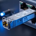
- DOM support: Digital Optical Monitoring via I2C/SFF DDM lets you alert on drift early; confirm your switch reads and logs DOM metrics.
- Compatibility with switch clocking: SyncE depends on how the switch uses recovered timing; confirm vendor documentation for SyncE mode support.
Specs comparison table: practical timing-capable optics baseline
The table below compares representative modules engineers use in timing over fiber designs. Values can vary by revision; treat them as starting points and confirm with vendor datasheets.
| Model example | Data rate | Wavelength | Reach class | Optical connector | Typical TX power | RX sensitivity | DOM | Operating temp |
|---|---|---|---|---|---|---|---|---|
| Cisco SFP-10G-SR | 10G | 850 nm | ~300 m (MM) | LC | ~ -1 to -9 dBm (varies) | ~ -9 to -12 dBm (varies) | Yes (DDM) | 0 to 70 C |
| Finisar FTLX8571D3BCL | 10G | 850 nm | ~300 m (MM) | LC | ~ -1 to -3 dBm (varies) | ~ -9 to -11 dBm (varies) | Yes (DDM) | -5 to 70 C (varies by label) |
| FS.com SFP-10GSR-85 | 10G | 850 nm | ~300 m (MM) | LC | ~ -1 to -3 dBm (varies) | ~ -9 to -11 dBm (varies) | Yes (DDM) | -5 to 70 C (varies by label) |
| Example 25G LR (vendor-specific) | 25G | 1310 nm | ~10 km (SM) | LC | ~ -1 to +2 dBm (varies) | ~ -14 to -18 dBm (varies) | Yes (DDM) | -5 to 70 C or wider |
Because timing over fiber is sensitive to stability, pay attention to datasheet language on jitter transfer, link delay stability, and recommended link budget margins. If the module vendor does not provide meaningful timing-related guarantees, treat it as an unknown risk and run a site acceptance test.
Reference standards to keep in view: IEEE 1588 (PTP) and Ethernet physical-layer timing behavior. For baseline concepts, consult IEEE 1588 standard pages and Ethernet timing background in IEEE 802.3 material IEEE 802.3 standard pages. For deployment notes, vendor datasheets and switch hardware configuration guides remain the most actionable documents.

Decision checklist: choosing optics that survive SyncE and PTP
Engineers rarely fail timing because they picked the wrong wavelength alone; they fail because of compatibility gaps, missing DOM telemetry, unsupported switch clock modes, or insufficient thermal margin. Use this ordered checklist to reduce surprises during commissioning.
- Distance and fiber type: Determine whether your link is MMF or SMF and compute worst-case attenuation including connectors and splitters.
- Interface compatibility: Confirm the transceiver supports the exact port type and optical standard your switch expects (including whether it is SR, LR, ER, or vendor-specific).
- Link budget margin: Reserve extra margin beyond nominal for aging, dirt, and seasonal temperature shifts. Keep a practical buffer (often several dB) so you do not operate near sensitivity limits.
- DOM and telemetry: Verify DOM is supported by your switch and that you can poll or receive alarms for optical power and temperature.
- SyncE clocking mode support: Ensure the switch supports SyncE in the topology you deploy (for example, whether it uses recovered clock on the selected ports).
- PTP hardware timestamping: Confirm whether your switch uses hardware timestamping for the relevant ports and whether it can act as a boundary clock or transparent clock.
- Operating temperature and airflow: Choose modules rated for the site ambient and confirm thermal design of the rack and optics cage.
- Vendor lock-in risk: Decide whether you accept OEM-only optics, or whether third-party optics are validated by your vendor or by your own test plan.
Real-world deployment scenario: 5G transport with timing over fiber
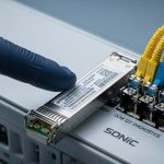
In a 3-tier 5G transport build, a team connects 48-port 25G ToR switches at the aggregation layer to a pair of spine switches using 25G LR optics over single-mode fiber. Each leaf-spine pair carries PTP to synchronize clocks across baseband processing servers, while SyncE provides continuous Ethernet-layer timing. They run link pairs with IEEE 1588 boundary clocks on the spine, and they require stable DOM readings for optical power drift and module temperature. During commissioning at a site where the rack ambient swings from 10 C to 45 C, they validate that PTP offset stays within an agreed window and that optics do not show rising error rates when the optical bias shifts seasonally.
Operationally, the team logs DOM every minute and correlates alarm thresholds with PTP offset changes. They also schedule a maintenance window to clean LC connectors after observing transient optical power dips that coincided with fiber management rework. The result is not perfect timing, but predictable behavior that can be monitored, alarmed, and corrected.

Common mistakes and troubleshooting when timing over fiber misbehaves
When timing over fiber degrades, it often looks like “random” jitter or intermittent PTP instability. In the field, you can narrow the cause quickly by checking a few common failure modes.
PTP offset oscillates after temperature change
Root cause: Optical module bias drift or marginal link budget causes subtle changes in effective performance across temperature, which can increase error recovery events and timestamp irregularities. Another contributor is poor airflow or a transceiver operating outside its rated temperature range.
Solution: Verify module datasheet temperature rating vs measured ambient at the port cage. Then check DOM temperature and optical power trend; clean connectors and re-seat optics. Re-run PTP measurement after stabilizing the rack temperature for at least one hour.
SyncE appears locked, but PTP still fails clock discipline
Root cause: SyncE and PTP are not automatically aligned; the switch may be in a clocking mode that does not provide consistent hardware timestamp reference. If the switch is misconfigured as a transparent clock when a boundary clock is required, the PTP path delay model can diverge.
Solution: Confirm the switch configuration for boundary clock vs transparent clock roles and ensure hardware timestamping is enabled for the PTP event messages. Validate with a controlled test: isolate one link, confirm PTP behavior, then expand to the full topology.
Works at install, degrades during later patching
Root cause: Connector contamination or fiber rework adds loss and increases optical errors, which can trigger retransmissions and disrupt assumptions about deterministic behavior. Timing can degrade even if the link stays “up” because the error correction and PHY behavior changes silently.
Solution: Use an optical power meter and an inspection scope on connector end faces after any patching work. Compare pre- and post-change DOM transmit/receive values; set alarms for both low power and rapid power drift.
Third-party optics show higher error counters on specific ports
Root cause: Compatibility mismatch between optics and switch vendor expectations, including DOM interpretation differences or stricter optical interface tolerances. Some optics may be electrically compatible but not validated for your specific switch silicon timing behavior.
Solution: Prefer modules validated by your switch vendor where possible, or run a structured optics acceptance test: error counters, DOM stability, temperature cycling, and PTP offset measurement under your real workload.
Cost and ROI reality for timing over fiber optics
Pricing depends on data rate, reach, and whether you choose OEM or third-party. Typical street ranges (at time of writing) often land around $40 to $120 per 10G module and $80 to $250 per 25G module, with higher pricing for extended reach or specialized variants. OEM optics may cost more, but they can reduce commissioning time and lower the probability of vendor-specific compatibility surprises.
TCO should include: module cost, failure rate and RMA logistics, labor time for swaps, and downtime risk during timing outages. A practical ROI model treats optics as “timing infrastructure”: if a single unstable link causes a site acceptance failure or a rework cycle, the labor and delay cost can dwarf the optics price difference. If you choose third-party optics, budget for a test harness and a staged rollout plan.

FAQ: timing over fiber with SyncE and IEEE 1588 PTP
Which transceiver features matter most for timing over fiber?
For timing over fiber, prioritize stable link behavior under temperature, correct optical standard compatibility, and DOM telemetry so you can detect drift early. Also confirm your switch supports SyncE clocking modes and PTP hardware timestamping for the ports used.
Do I need the transceiver to advertise PTP-specific performance?
Most optics datasheets do not provide PTP-specific timing guarantees. Instead, engineers validate in-system using hardware timestamping and boundary clock configuration, then correlate PTP offset and optical DOM trends during temperature and load changes.
Is SyncE alone enough for 5G timing?
SyncE provides physical-layer timing continuity, but many 5G transport designs still use IEEE 1588 PTP for finer alignment across domains and path variations. The best approach depends on your network architecture and the synchronization strategy documented by your equipment vendors.
Can I mix OEM and third-party optics in the same timing domain?
You can, but only if you have validated compatibility and stability. Mixed optics can behave differently in DOM reporting, power ramp characteristics, and error recovery patterns, which can complicate PTP discipline and alarm thresholds.
What should I monitor during acceptance tests?
Monitor PTP offset and mean path delay alongside DOM metrics (TX power, RX power, module temperature). Also track PHY or switch interface error counters, and run the test through the site’s expected temperature range rather than only at room conditions.
When timing fails, where do I look first?
Start with switch configuration: boundary clock vs transparent clock, hardware timestamping enablement, and clocking mode for SyncE. Then check optics basics: optical power margin, connector cleanliness, DOM drift, and temperature rating alignment with the rack environment.
If you want the next step, map your current optics and switch settings to the checklist above, then run a staged acceptance test that correlates PTP behavior with DOM telemetry. For more on synchronization architecture, see IEEE 1588 PTP boundary clock configuration for practical configuration patterns.
Author bio: I have deployed timing over fiber in 5G transport labs and production racks, measuring PTP offsets against DOM and switch hardware timestamping behavior during temperature cycling. My work focuses on operational verification, not theoretical sync claims, and on reducing commissioning time through repeatable test plans.