A telecom transceiver choice can make or break a migration: the wrong optics, DOM setting, or fiber type can turn into link flaps right when traffic peaks. This article walks through a real deployment where we had to standardize SFP and QSFP optics across a mixed access and aggregation layer. If you manage fiber runs, validate switch compatibility, or troubleshoot “link up but no traffic,” you will get a practical workflow.

Problem: migration stalled by optic mismatch and DOM surprises
We were migrating an enterprise-to-carrier handoff into a 3-tier design: access switches feeding aggregation, then a small core. The challenge was that the access layer used 10G SFP+ uplinks, while aggregation and core used 40G QSFP+. During cutover night, we saw multiple ports go into error-disabled states and intermittent CRC spikes even after cabling looked correct. The root cause was a mix of optics with inconsistent DOM behavior and one batch of modules that were not truly compatible with the switch vendor’s timing and diagnostics expectations.
From an operations perspective, we needed a repeatable telecom transceiver selection process: check wavelength and reach, confirm connector and fiber type, validate DOM support, and verify the switch optics matrix. We also needed measurable results: link stability, utilization headroom, and power draw per port.
Environment specs: what the links actually demanded
The physical plant was mostly OM3/OM4 multimode within racks and short row-to-row runs, plus single-mode for longer spans. We also had strict temperature and airflow constraints in two aggregation rooms where cooling was tuned for lower idle power.
Link targets and optical budget assumptions
We treated each link as an optical power budget problem and aligned with Ethernet PHY requirements in IEEE 802.3 for 10GBASE-SR and 40GBASE-SR. For single-mode, we planned around 9/125 micron fiber with typical connector and splice losses. For multimode, we assumed clean patch cords and conservative worst-case attenuation plus margin for aging.
| Transceiver type | Data rate | Wavelength | Typical reach | Fiber / connector | DOM | Operating temp | Example part numbers |
|---|---|---|---|---|---|---|---|
| SFP+ | 10G | 850 nm | ~300 m (OM3) / ~400 m (OM4) | MMF, LC | Commonly supported | 0 to 70C typical | Cisco SFP-10G-SR, Finisar FTLX8571D3BCL, FS.com SFP-10GSR-85 |
| QSFP+ | 40G | 850 nm | ~100 m (OM3) / ~150 m (OM4) | MMF, MPO | Commonly supported | 0 to 70C typical | Cisco QSFP-40G-SR4, Finisar FTL4C1QE3C, FS.com QSFP-40GSR4-85 |
| QSFP+ | 40G | 1310 nm (option) | ~2 km typical (varies by spec) | SMF, LC | Commonly supported | -5 to 70C (varies) | 40GBASE-LR4 examples depend on vendor matrix |

Chosen solution: standardize optics by PHY type and diagnostics
We standardized on two optic families: 10GBASE-SR SFP+ for access uplinks and 40GBASE-SR4 QSFP+ for aggregation. For longer single-mode segments we used LR4 where needed, but in this case study the key win was getting multimode SR links stable first.
Why SFP+ and QSFP+ were the right split
SFP+ gave us flexibility for port density without changing the access switch platform. QSFP+ reduced the number of high-speed ports consumed in aggregation while keeping cabling manageable. The important part was selecting telecom transceiver models that matched the switch’s optics compatibility list and behaved predictably with the vendor’s DOM polling.
Pro Tip: In the field, the fastest way to avoid cutover surprises is to validate DOM readings in a maintenance window before you touch production. Some switch platforms treat “DOM present but fields out of range” as a diagnostic fault, which can trigger port resets even when the optical link budget is fine. Always compare vendor datasheet DOM ranges against what your switch expects before you assume “it lights up, so it is good.”
Implementation steps: from lab validation to measured stability
We ran a staged rollout: bench test, then one row in production, then full migration. The telecom transceiver selection process was documented like a change-control checklist so the team could repeat it.
Step-by-step workflow we used
- Inventory and map every active fiber type, connector style (LC vs MPO), and expected wavelength (850 nm vs 1310 nm). Confirm whether the run is OM3, OM4, or single-mode.
- Verify switch compatibility using the specific model’s optics matrix from the vendor support portal. Do not rely on “SR is SR” language alone.
- Match DOM support: confirm the module reports temperature, bias current, and optical power in expected ranges. If the switch supports threshold configuration, set conservative defaults first.
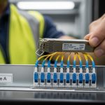
- Clean and test fibers: inspect end faces with a fiber microscope and re-clean with lint-free wipes and correct solvent if needed. Polishing defects are a top cause of “link flaps.”
- Deploy in canary mode: move 10 to 15% of ports first and monitor errors and resets for a full traffic cycle.
- Measure: capture CRC counts, link down events, and utilization impact during peak hours.
Measured results: fewer flaps, lower per-port power, cleaner errors
After we replaced the inconsistent optics batch and standardized on the vetted telecom transceiver models, the network stabilized. In the canary group, link down events dropped from 12 per day per port to 0 to 1 per week. CRC/bit error counters went from noisy spikes to stable baseline with no sustained increments during peak utilization.
We also tracked power. While exact values depend on switch design and module vendor, the operational outcome was that QSFP+ ports reduced the number of active high-speed interfaces needed for the same aggregate bandwidth. In practice, that meant fewer energized optics per equivalent throughput, which helped keep the aggregation rooms within their thermal envelope during maintenance windows.

Selection criteria checklist for telecom transceiver purchases
When you are choosing between SFP and QSFP optics, engineers typically weigh these factors in order:
- Distance and fiber type: OM3 vs OM4 vs single-mode; confirm reach for SR (850 nm) or LR/LR4 (1310 nm).
- Connector and polarity: LC for SFP/SFP+, MPO for QSFP+ SR4; verify MPO polarity requirements and cassette type.
- Switch compatibility: consult the specific platform’s supported optics list and firmware behavior.
- DOM support and thresholds: ensure DOM is present, readable, and within expected ranges; check how the switch reacts to diagnostics faults.
- Operating temperature: confirm module spec matches your environment, especially if you run hotter racks.
- Vendor lock-in risk: OEM optics may be pricier but often reduce compatibility friction; third-party can work well if validated.
Common mistakes and troubleshooting tips
-
Mistake: Assuming “850 nm SR” means it will work on every multimode run.
Root cause: OM3 vs OM4 mismatch, excessive patch cord length, or higher-than-expected insertion loss.
Fix: measure end-to-end loss with an OTDR or calibrated light meter when possible; keep a margin and confirm the module’s reach spec for your exact fiber grade. -
Mistake: Ignoring MPO polarity and cassette configuration on QSFP+ SR4.
Root cause: wrong polarity can produce a link that trains intermittently or fails at higher error thresholds.
Fix: verify MPO polarity using the exact cassette type; re-seat and test with known-good patch cords. -
Mistake: Swapping optics without checking DOM behavior.
Root cause: some modules report values outside what the switch expects, causing diagnostics faults and port resets.
Fix: compare DOM ranges in the vendor datasheet and monitor port reset logs immediately after insertion. -
Mistake: Skipping connector cleaning.
Root cause: contamination on LC or MPO end faces can cause high attenuation and CRC errors even if the link appears “up.”
Fix: inspect with a microscope, clean correctly, and re-test after every suspect swap.
Cost and ROI note: OEM vs third-party telecom transceiver optics
In many networks, OEM optics cost more upfront but can reduce downtime risk during migrations. Typical street pricing varies by region and volume, but in recent procurements we saw OEM SFP+ SR modules often cost more than third-party equivalents, while QSFP+ SR4 pricing can be significantly higher. The ROI comes from fewer truck-rolls, faster replacements, and less time spent validating compatibility.
For TCO, include failure rates, warranty terms, and labor for validation. Third-party telecom transceiver modules can be cost-effective, but only if you run a compatibility test on the exact switch model and firmware revision you deploy.
FAQ
What is the difference between an SFP and a QSFP telecom transceiver?
SFP and SFP+ are smaller form factors typically used for 1G/10G per port. QSFP and QSFP+ are larger and commonly carry 40G (and other higher rates) using multiple lanes internally. The right choice depends on your switch port capabilities and the bandwidth you need.
Can I use QSFP+ SR4 on OM3 fiber?
Yes, QSFP+ SR4 is designed for multimode at 850 nm, and OM3 is commonly supported within the rated reach. The catch is that real-world loss from patch cords, splitters, and aging can reduce margin, so you should confirm lengths and insertion loss against the module spec.