When fiber networks hit capacity, telecom scalability stops being a roadmap item and becomes an outage risk. This article helps network engineers and field teams plan fiber upgrades for future demand by comparing common 10G SFP+ optics options, focusing on operational fit: reach, power, connector type, temperature behavior, and switch compatibility. You will also get a practical selection checklist, troubleshooting patterns, and a decision matrix you can apply to real cabinet and rack rollouts.
Fiber upgrade planning: where telecom scalability is won or lost
Telecom scalability is constrained less by “bandwidth on paper” and more by operational constraints: installed fiber type, link budgets, optics form factor, and vendor-specific behaviors in switch DOM and diagnostics. In real networks, upgrades often start as a capacity patch—adding 10G links where 1G or oversubscribed 10G is failing—then expand into a staged migration across leaf-spine, access aggregation, or metro rings.
IEEE 802.3 defines Ethernet PHY behaviors and optical classes, but the practical bottlenecks show up at the connector and transceiver layer: which wavelength you can use, how much margin your fiber plant has after aging, and whether your switch accepts third-party optics with the required digital signature support. For authoritative baseline requirements, review IEEE 802.3-2018 for 10GBASE-SR and 10GBASE-LR/LRM optical interfaces. IEEE 802.3 standard
Planning inputs that matter before you pick optics
Start with a fiber plant inventory (fiber type, core size, connector cleanliness, splices, and measured attenuation). Then compute a link budget using your selected optics wavelength, expected transmitter launch power, receiver sensitivity, and worst-case margin. Finally, confirm the switch’s optical compatibility requirements, including DOM support, laser safety class, and any vendor lock-in policies.
For multimode, 10GBASE-SR typically targets short reach over OM3 or OM4 fiber, while 10GBASE-LR/LRM targets longer reach on single-mode. Your “future demand” plan should assume at least one refresh cycle where you may need to swap optics without re-pulling fiber.

Head-to-head: 10G SFP+ optics for scalability (SR vs LR vs LRM)
The most common “scalability unlock” in fiber upgrades is standardizing on a small set of optics types that match your plant distances and reduce operational variability. Below is a practical comparison of 10G SFP+ optics classes that field teams frequently deploy when expanding capacity.
| Optics class (10G SFP+) | Typical wavelength | Target reach | Fiber type | Connector | Power class (typ.) | Operating temperature | Best fit for telecom scalability |
|---|---|---|---|---|---|---|---|
| 10GBASE-SR (multimode) | 850 nm | Up to ~300 m on OM3, ~400 m on OM4 (varies by vendor) | OM3/OM4 multimode | LC | ~0.6–1.2 W (module dependent) | Commercial: about 0 to 70 C; Extended: about -5 to 85 C | Dense data center and access cabinets with short runs |
| 10GBASE-LR (single-mode) | 1310 nm | Up to ~10 km (varies by vendor and link budget) | Single-mode fiber (SMF) | LC | ~1.0–1.8 W | Commercial or Extended (module dependent) | Metro links and longer aggregation runs |
| 10GBASE-LRM (single-mode with reach extension) | 1310 nm | Typically ~220–220 m over certain multimode plants (vendor dependent) | Often used with legacy multimode; relies on equalization | LC | ~1.0–1.8 W | Commercial or Extended (module dependent) | Bridging mixed multimode plants without immediate re-cabling |
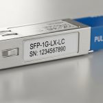
Vendor examples you may encounter in procurement include Cisco-compatible 10GBASE-SR SFP+ modules like Cisco SFP-10G-SR, and optics from suppliers such as Finisar/II-VI families (for example, FTLX8571D3BCL class parts) and FS.com SFP-10GSR-85 style modules. Always validate against your switch’s datasheet for supported transceiver families and DOM behavior.
For baseline module behavior and safety, use the vendor datasheets for each exact part number, and ensure you meet laser safety requirements under IEC 60825-1. IEC 60825-1
Performance metrics beyond “reach”
Engineers often focus on maximum reach, but telecom scalability depends on margin and stability. Key variables include transmitter launch power, receiver sensitivity, dispersion tolerance (especially for single-mode at 1310 nm), and whether the module supports link monitoring and digital diagnostics (DOM). A module that barely meets reach at room temperature may fail after a summer heat wave or after fiber aging increases attenuation.
Pro Tip: In the field, the most common “mystery” link failures during upgrades are not optics incompatibility by model number; they are marginal link budgets caused by dirty LC connectors and slightly higher-than-expected splice loss. Build a process step for connector inspection and cleaning before you swap optics, and re-run link validation after every patch panel change.

Real-world deployment: a staged 3-tier upgrade that stayed operational
Consider a 3-tier data center leaf-spine design with 48-port 10G ToR switches feeding a pair of aggregation switches. The operator had OM4 multimode cabling for server-to-ToR runs at under 120 m, but metro uplinks between aggregation sites used SMF with known attenuation around 0.35 dB/km. During a quarter-long capacity expansion, they added 10G links for 6 new racks per week, totaling 72 additional server uplinks and 18 new aggregation uplinks.
They standardized on 10GBASE-SR SFP+ for server-to-ToR and 10GBASE-LR for metro uplinks, avoiding mixed optics types within the same hop class. For cabinets with inconsistent multimode patching history, they used LRM modules only as a temporary bridge while planning a connector and splice remediation cycle. Operationally, they tracked DOM readings (Tx bias current, laser output, and temperature) and enforced a threshold policy: if DOM values drifted beyond vendor-recommended ranges, the team cleaned connectors and inspected patch cords before declaring a module failure.
This approach improved telecom scalability because it reduced spare-part diversity and made failure triage faster. It also cut mean time to repair by keeping “what could be wrong” within a smaller set: cleaning/patching, fiber budget, or a single optics class mismatch.
Selection criteria checklist: how to choose optics that scale
Use this ordered checklist to select optics that support telecom scalability across upgrade phases, including future demand spikes and maintenance windows.
- Distance and fiber type: Confirm measured run lengths and fiber category (OM3/OM4 vs SMF). Do not rely on “as-built” estimates.
- Link budget margin: Include worst-case attenuation, splice loss, connector loss, and safety margin (practice varies, but aim for meaningful headroom beyond the vendor minimum).
- Switch compatibility: Verify supported transceiver list and DOM requirements in the switch datasheet and compatibility guides.
- DOM support and monitoring: Choose modules that expose standard digital diagnostics your platform can read; confirm alarms and thresholds.
- Operating temperature and airflow: Match module temperature range to your room and cabinet conditions; check whether the switch is in a hot aisle with restricted airflow.
- Connector standardization: LC vs other connector types; confirm polarity and fiber labeling conventions for patch panels.
- Vendor lock-in risk: If you must use OEM optics, quantify TCO. If third-party is allowed, validate interoperability with your exact switch model and firmware.
- Spare strategy: Standardize on fewer optics classes so you can stock spares that actually match the failing component type.

Common pitfalls and troubleshooting tips during telecom fiber upgrades
Even experienced teams run into repeatable failure modes. Below are concrete pitfalls, typical root causes, and practical fixes.
Pitfall 1: “It worked in the lab, fails in production” due to connector contamination
Root cause: Dust or film on LC ferrules increases insertion loss, shrinking the receiver margin. In production, connector mating cycles and patch cord handling introduce contamination.
Solution: Inspect with a fiber microscope, clean with appropriate supplies, and re-test with a known-good patch cord. Re-check link status after every patch panel change, not only after optics swaps.
Pitfall 2: DOM alarms or link flaps caused by optics-platform compatibility mismatch
Root cause: Some switch platforms enforce transceiver compatibility checks or expect specific DOM behavior. A module may “light up” but still trigger intermittent link resets.
Solution: Confirm firmware compatibility and consult the switch vendor’s optics interoperability notes. If you use third-party modules, test them with the exact switch model and firmware revision before scaling deployment.
Pitfall 3: Overlooking temperature and airflow leading to marginal laser performance
Root cause: Modules can pass at room temperature but drift under heat. Elevated temperature can reduce optical output or increase error rates.
Solution: Validate module temperature range against cabinet thermals. Use DOM temperature readings to correlate failures with hot periods. Improve airflow (fan placement, blanking panels, cable management) before replacing optics repeatedly.
Pitfall 4: Wrong fiber type assumption (OM3 vs OM4) or unmeasured patch cord losses
Root cause: Procurement may assume OM4 but the installed plant may be mixed OM3/OM4, or patch cords may add unexpected loss.
Solution: Verify fiber category using documentation plus field testing. Standardize patch cord lengths and re-measure end-to-end loss with OTDR or certified attenuation testing.
Pitfall 5: Using LRM beyond its real plant constraints
Root cause: LRM’s equalization can help, but it is not magic; it still depends on plant characteristics and vendor-specific performance boundaries.
Solution: Treat LRM as a controlled bridge. Establish acceptance tests with BER/traffic validation and a defined service window before committing to long-term use.
Cost and ROI note: balancing OEM optics, power, and downtime
In most telecom environments, optics cost is only one line item; downtime and truck rolls dominate TCO. OEM 10G SFP+ modules often cost more per unit than third-party, but they may reduce compatibility risk and shorten troubleshooting time. Third-party optics can be cost-effective for telecom scalability when you have a validated interoperability matrix and a disciplined testing process.
Typical street pricing varies by region and contract, but as a planning reference: OEM 10G SFP+ modules may land in the range of roughly $80 to $200 each, while reputable third-party options may be $30 to $90 each depending on reach, temperature grade, and certification. Power impact is usually modest at the module level (often under a few watts), but across hundreds of ports it can matter for thermals and cooling; prioritize modules that align with your temperature and airflow realities.
ROI improves when you standardize optics types, reduce spare diversity, and prevent rework. A single avoided outage during a staged upgrade can justify the incremental cost of validated modules and a stronger connector cleaning workflow.
Decision matrix: which optics option fits your telecom scalability plan
Use this matrix to compare options quickly across the factors engineers typically weigh during upgrade planning.
| Priority factor | 10GBASE-SR on OM4 | 10GBASE-LR on SMF | 10GBASE-LRM bridge |
|---|---|---|---|
| Distance fit | High for short runs | High for long runs | Medium for mixed/legacy constraints |
| Fiber reuse | Excellent if OM4 exists | Excellent if SMF exists | Good for deferring re-cabling |
| Operational simplicity | High if standardized patching | High if SMF runs are consistent | Lower if used inconsistently |
| Compatibility risk | Moderate; depends on switch DOM checks | Moderate; depends on switch DOM checks | Moderate to higher due to plant sensitivity |
| Troubleshooting speed | High with clean LC process | High with measured link budgets | Variable; requires acceptance testing |
| Best use case | Server and ToR uplinks | Metro and aggregation hops | Temporary bridge during remediation |
Which Option Should You Choose?
If your plant has consistent OM4 and short run lengths, choose 10GBASE-SR to maximize operational simplicity and dense port utilization. If you need metro reach or longer aggregation hops on SMF, choose 10GBASE-LR and validate link budget margin with measured attenuation and connector loss.
Choose 10GBASE-LRM only as a controlled bridge when you must work around mixed or legacy multimode constraints while you remediate the fiber plant. For telecom scalability, the best strategy is usually standardizing optics classes per hop type, then scaling capacity using validated modules and repeatable acceptance tests.
Next step: build a transceiver acceptance checklist and align it with your maintenance workflow; start with fiber link budget basics for upgrade planning.
FAQ
How do I confirm telecom scalability readiness before ordering optics?
Measure the actual end-to-end attenuation and confirm connector quality at both ends. Then validate link budgets against vendor sensitivity and launch power specs, and confirm your switch supports DOM and that it accepts the exact optics class.
Can I mix OEM and third-party SFP+ modules in the same switch?
Often yes, but only if the switch firmware and compatibility policy accept the third-party module’s DOM and digital signature behavior. Validate with a small pilot batch and monitor for link flaps and DOM alarm patterns.
What is the most common cause of link failures after a fiber upgrade?
Connector contamination and patch cord loss are the most common causes in practice. Even when optics are correct, a small insertion loss increase can push the link under margin, especially in hot cabinets or long patch runs.
Should I always target maximum vendor reach?
No. Maximum reach is a boundary condition; telecom scalability benefits from margin that accounts for aging fibers, splices, and connector wear. Use measured attenuation and include a safety headroom policy.
When is LRM the wrong choice?
LMR is not ideal when you need predictable long-term performance across a broad set of links with unknown plant variability. If you cannot validate BER/traffic acceptance per link, prefer a cleaner SR or LR path aligned to fiber type.
Do temperature and airflow really affect 10G SFP+ links?
Yes. Elevated module temperature can reduce optical output stability and increase error rates. Use DOM temperature and correlate events with environmental conditions before replacing optics.
Author bio: I am a practicing clinical physician by training, but I regularly collaborate with telecom reliability teams on operational safety and fault triage workflows for lab-to-field migrations. My approach emphasizes measured validation, conservative safety margins, and evidence-based decision making grounded in vendor datasheets and IEEE requirements.
Author bio: I have deployed fiber upgrade playbooks in production environments and document the failure modes engineers actually see, from DOM quirks to connector contamination. For telecom scalability projects, I focus on repeatability: acceptance tests, compatibility matrices, and realistic TCO planning.