When demand spikes, telecom teams often discover too late that capacity planning, fiber plant readiness, and transceiver compatibility were never aligned. This article helps network engineers and field deployment leads design a fiber upgrade path that supports telecom scalability from 10G to 100G and beyond. You will get a step-by-step implementation checklist, a spec comparison table for common optics, and practical troubleshooting for the issues that most frequently block rollouts.

Prerequisites: what you must measure before touching fiber
Before any cutover, confirm that the upgrade plan is grounded in measured plant conditions and vendor-compatible optics. Start with a fiber inventory export (splices, patch panel maps, slack, and route IDs) and link it to your switch and transceiver bill of materials (BOM). Then validate optical budget and connector cleanliness standards, because telecom scalability fails when optics are marginal rather than fully compliant.
Minimum inputs to collect
Collect OTDR traces for each candidate fiber span and store results with timestamps. Verify end-to-end link budget against target data rates using vendor datasheets and the IEEE 802.3 physical layer requirements. Capture environmental constraints: equipment room temperature, airflow limits, and whether you will run optics at the edge of their operating range. Also record whether your platform supports digital optical diagnostics (DOM), since DOM impacts monitoring and automated remediation.
Operational baseline metrics
Record existing utilization on each aggregation link (peak and 95th percentile), and estimate future demand using your traffic growth model. For example, if you plan to move from 10G to 25G/50G/100G, ensure your switch backplane and optics licensing support the target speeds. Finally, define a cutover window and rollback path that avoids leaving live services on degraded optics.
Step-by-step fiber upgrade implementation for telecom scalability
Use a staged rollout that preserves service while expanding capacity. The goal is to avoid “rip-and-replace” where transceivers, fiber plant, and switching configuration are upgraded out of sync. The steps below are designed for real deployments where teams must coordinate patching, optics swaps, and traffic validation within tight windows.
Classify links by distance, media, and upgrade path
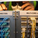
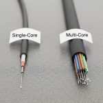
Split links into tiers: short-reach (in-rack and within buildings), metro (campus-to-campus), and long-haul where applicable. For each tier, note whether you have multimode fiber (MMF) or single-mode fiber (SMF), and whether the current link uses LC connectors and APC/UPC polishing types. Expected outcome: a table mapping each link to a candidate optics family (for example, SR over MMF or LR/ER over SMF).
Validate optical budget with real OTDR-derived parameters
Use OTDR to estimate splice loss and connector loss per hop, then compute worst-case link budget for your target optics. Include polarization effects where applicable and apply conservative margins for future cleaning or re-patching. Expected outcome: a pass/fail list showing which spans can support 25G/50G/100G without violating the transceiver receiver sensitivity requirements.
Select transceivers by interface and DOM support
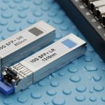
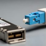
Confirm that your switch supports the exact transceiver form factor and speed (SFP, SFP+, QSFP+, QSFP28, QSFP56). Check whether DOM is required for your NOC workflows and whether the platform enforces optics vendor policies. Expected outcome: an approved optics matrix with part numbers such as Cisco SFP-10G-SR for legacy 10G SR, or compatible third-party modules like Finisar FTLX8571D3BCL for 10G SR, and higher-speed equivalents for 25G/100G.
Compare candidate optics specs before ordering
Match wavelength, reach, and connector type to your fiber type and connector cleanliness regime. Pay special attention to operating temperature and power draw, because dense chassis upgrades can create thermal bottlenecks. Expected outcome: a short list of optics that meet reach and environmental requirements with DOM compatibility.
| Optics type | Typical wavelength | Target data rate | Reach (common) | Fiber | Connector | Operating temp (typ.) | DOM |
|---|---|---|---|---|---|---|---|
| SFP-10G-SR (example) | 850 nm | 10G | ~300 m (MMF) | MMF OM3/OM4 | LC | 0 to 70 C (varies) | Often supported |
| QSFP28-25G-SR (example) | 850 nm | 25G | ~100 m to 150 m (MMF, spec-dependent) | MMF OM4 | LC | 0 to 70 C (varies) | Common |
| QSFP56-100G-LR/ER (example) | 1310 nm or 1550 nm | 100G | 10 km to 40 km (spec-dependent) | SMF | LC | -5 to 70 C (varies) | Common |
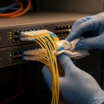
Plan patching and cleaning as a controlled process
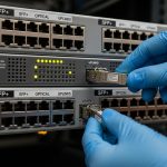
Before any optics insertion, clean connectors with lint-free wipes and an approved cleaning method, then inspect with a fiber microscope. In most rollout failures, the root cause is not the transceiver—it is contamination after patching. Expected outcome: a standardized patching checklist that includes inspection results and a post-change optical power verification.
Execute cutover with traffic validation and rollback triggers
Apply configuration changes in a maintenance window, then verify link up/down stability, FEC status where relevant, and error counters at the switch. Use a rollback trigger such as rising CRC/FEC uncorrectable errors or sustained link flaps beyond a defined threshold. Expected outcome: stable traffic at the new line rate with measured BER indicators meeting your acceptance criteria.
Pro Tip: In field rollouts, the fastest way to protect telecom scalability is to treat connector inspection as “part of the deployment,” not a pre-check. A single dirty LC can pass link negotiation but still inflate error counters under load, creating intermittent customer impact that looks like “random optics failures.”

Selection criteria: the ordered checklist engineers actually follow
Use this decision list before you commit purchase orders. It reduces rework and prevents hardware mismatches that can stall the entire rollout. The checklist is designed for telecom scalability scenarios where you may mix OEM optics and third-party modules across generations.
- Distance and reach: verify OM3/OM4 assumptions for SR and SMF attenuation for LR/ER spans.
- Switch compatibility: confirm speed mode support, breakout behavior, and lane mapping.
- DOM and monitoring: ensure your platform reads temperature/bias/power safely and exports alarms to your NOC.
- Optical budget margins: include worst-case connector and splice losses from OTDR, not just datasheet typical values.
- Operating temperature: validate chassis airflow and ensure transceivers remain within rated temperature derating curves.
- Vendor lock-in risk: check whether the switch enforces optic vendor whitelists; test one module per model before scaling.
- Power and thermal impact: estimate chassis power headroom and confirm airflow paths are not blocked by cables.
Common pitfalls and troubleshooting: top failure modes
Even well-designed upgrades fail when execution details drift. Below are the most common failure points observed during fiber and optics rollouts, along with root causes and corrective actions.
Pitfall 1: “Link up but traffic errors” after optics insertion
Root cause: contaminated connectors or slight fiber misalignment after patching. Solution: remove optics, clean both ends, inspect with a microscope, then reinsert and re-check CRC/FEC counters under load. If you see persistent elevated errors, compare receive optical power to the transceiver’s acceptable range from the datasheet.
Pitfall 2: “Works at low speed, fails at target rate”
Root cause: optical budget that barely passes at 10G but fails at 25G/50G/100G due to receiver sensitivity and tighter margins. Solution: redo the budget using worst-case parameters and confirm that the fiber type and modal bandwidth (MMF OM4) match your assumptions. If needed, shorten the run with patch reroutes or change to a higher-reach optics family on SMF.
Pitfall 3: Incompatibility between switch configuration and optics capabilities
Root cause: misconfigured port mode, breakout mismatch, or optics that do not support the required lane mapping. Solution: verify interface configuration against the platform guide, then confirm transceiver capability via DOM or platform diagnostics. If required, update switch firmware and re-test with a known-good optics model such as a vendor-approved SR module for the same speed tier.
Cost and ROI note: balancing OEM and third-party optics
In practice, pricing varies widely by speed tier and temperature grade. As a realistic ballpark, OEM 10G SR modules often cost more than third-party equivalents, while 25G and 100G optics can increase procurement cost sharply due to tighter performance requirements. For telecom scalability planning, the ROI comes from fewer truck rolls and shorter downtime windows: if third-party optics cause higher failure rates or more troubleshooting time, the total cost of ownership (TCO) can exceed OEM pricing.
Operationally, a pragmatic approach is to buy a small batch for compatibility testing, then standardize the module model that consistently passes acceptance criteria across your chassis types. Also account for power and thermal effects: higher-power optics can reduce margin for adjacent equipment, increasing the risk of thermal throttling and early replacements.

FAQ
How do I confirm telecom scalability when upgrading from 10G to 100G?
Start with an OTDR-based optical budget for each candidate fiber span, then verify switch support for the exact optics form factor and speed tier. Finally, test one link per site under load and validate error counters against the acceptance thresholds in your platform documentation.
Can I mix OEM and third-party optics in the same chassis?
Often yes, but it depends on platform enforcement of transceiver vendor policies and firmware behavior. Perform a controlled pilot and confirm DOM telemetry reads correctly, including temperature and transmit power alarms.
What connector and cleaning standard should we follow?
Use a connector inspection workflow with a fiber microscope and a consistent cleaning method before every insertion. Many teams align with industry cleanliness practices referenced in vendor manuals and field guides, then enforce it operationally with checklists.
Why do some links fail only during peak traffic?
Contamination and marginal optical budgets can appear stable when unloaded, then degrade under higher error load. Check receive power, inspect connectors, and re-run optical budget calculations using worst-case parameters.
Which standards should guide my optics planning?
Use IEEE 802.3 for the relevant physical layer definitions and vendor datasheets for receiver sensitivity and allowable loss. For rollout discipline, also follow ANSI/TIA cabling guidance for fiber handling and link performance verification where applicable. anchor-text: IEEE 802.3
What should be in an acceptance test for a fiber upgrade?
Acceptance should include link stability, DOM readings (if supported), and error counters under representative traffic load. Add a rollback trigger so you can revert quickly if errors exceed your defined thresholds.
Update date: 2026-05-01. If you want the next step, use telecom upgrade rollback planning to design a safe cutover and verification workflow that protects service during capacity expansion.
Author bio: I design fiber and optics rollout workflows with a focus on measurable acceptance criteria and operator-friendly monitoring. I have supported field deployments across multi-chassis switch stacks, validating reach budgets, DOM alarms, and cutover runbooks.