Many SMB networking teams are being asked to “move to 800G” before they have a repeatable migration plan. This article helps IT managers and field engineers translate 800G migration into measurable steps: port mapping, optics selection, fiber readiness, and operational risk controls. You will get an ROI-oriented checklist, a troubleshooting section grounded in common transceiver and cabling failures, and a clear decision path for switch compatibility.
Why 800G is different in SMB networking (and where ROI comes from)
At 800G, the bottleneck often shifts from “can we light the link” to “can we scale the operational system around it.” In SMB networking, that means fewer spare optics in the budget, tighter maintenance windows, and limited staff time for troubleshooting. The ROI usually comes from higher throughput per rack unit and fewer parallel links, but only if your cabling plant and switch port density can actually absorb the change.
From a standards perspective, 800G Ethernet aligns with IEEE 802.3 for high-speed physical layers and the associated link behavior; however, real deployments are still governed by vendor-specific optics support and transceiver programmability. For example, OEM implementations may require specific DOM handling and may enforce lane mapping assumptions that affect which optics work reliably. Practical planning therefore treats the switch plus optics plus fiber as one system, not three independent parts.
Migration triggers that show up in real SMB environments
In a typical SMB data center or hosted environment, triggers include rapid VM growth, backup windows shrinking, and storage replication needing more sustained bandwidth. A common pattern is moving from 25G or 100G uplinks to 200G/400G and then planning 800G for leaf-spine uplinks or high-throughput storage fabrics. The migration becomes urgent when you see sustained utilization above 70% on existing uplinks and queueing delays that break application SLOs.
Pro Tip: In many field installs, the first “800G problem” is not the transceiver at all—it is the optics compatibility mode and cleaning state. If you standardize on vendor-supported optics profiles and enforce a fiber cleaning workflow before every hot swap, you can cut repeat failures dramatically during early rollout.

Key technical decisions: ports, optics type, reach, and DOM
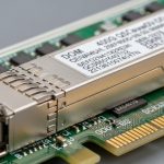
800G deployments typically use QSFP-DD or OSFP form factors depending on the switch generation, with multi-lane signaling over fiber. For short-reach data center links, the most cost-effective path is usually SR8 style optics using multi-fiber connectors such as MPO/MTP. But the exact reach and lane behavior depend on both the optics module model and the switch’s supported transceiver list.
For SMB networking teams, the “best practice” is to decide the target topology and link budget first, then select optics that match both reach and connector type. If you plan to reuse existing OM4 or OM3 cabling, verify that your measured link attenuation and polarity are compatible with the specific 800G SR optics. Also validate that the switch supports the transceiver’s digital diagnostics via DOM (or equivalent) and that it can handle any required settings.
What to verify in datasheets and switch compatibility matrices
Engineers typically confirm wavelength band (even for “SR” modules), target reach, optical power levels, and connector type. They also check operating temperature range because SMB networking sites may run hot in closets or during summer HVAC failures. Finally, confirm that the switch supports the module vendor and model, not just the “form factor,” because compatibility lists can be strict.
| Transceiver / Spec Item | Example 800G Short-Reach (SR8-style) | Example 800G Long-Reach (LR8-style) |
|---|---|---|
| Data rate | 800G (multi-lane Ethernet) | 800G (multi-lane Ethernet) |
| Wavelength band | Nominal “SR” short-reach optics (multi-lane) | Nominal long-reach band (multi-lane) |
| Reach class | ~100 m over OM4 typical for SR8-class optics (verify vendor) | ~10 km typical for LR8-class optics (verify vendor) |
| Connector | MPO/MTP (often 8-fiber or structured mapping) | LC or MPO depending on module family |
| Operating temperature | Commonly 0 to 70 C or vendor-specific industrial options | Commonly 0 to 70 C or vendor-specific industrial options |
| DOM / diagnostics | Digital optical diagnostics required for monitoring and alerts | Digital optical diagnostics required for monitoring and alerts |
| Typical power & cooling impact | Lower than long-reach but still meaningful for dense chassis | May increase power draw depending on design |
Because vendors vary, treat the table as a planning template. For concrete module compatibility, reference switch manuals and vendor optics lists, such as Cisco, Juniper, Arista, or Broadcom-based platforms, plus module datasheets like those from Finisar and FS. For general Ethernet physical layer context, consult [Source: IEEE 802.3] and vendor transceiver datasheets for the specific reach and connector requirements.
External authority links you may find useful include: IEEE 802.3 standard portal and vendor documentation for module compatibility and DOM behavior, such as: FS.com 800G QSFP-DD optics catalog and Finisar transceivers and optics information (use these to locate datasheets, not as a compatibility guarantee).

Migration blueprint for SMB networking: a phased, measurable approach
An SMB networking 800G migration should be staged so you can learn quickly without risking the entire network. The goal is to reduce unknowns: optics compatibility, fiber cleanliness, port mapping, and operational runbooks. A practical approach is to pilot on a subset of leaf uplinks or a single storage fabric path first, then expand after validation.
Phase 1: Inventory and readiness scoring (1 to 2 weeks)
Start by mapping every candidate port to its destination and documenting current utilization. For example, if you run a leaf-spine topology with 48 ToR switches each connecting to 2 spine switches, you might have 96 uplink pairs to consider. Inventory the existing fiber types (OM3/OM4), connector families (MPO vs LC), and patch panel structure. Then score each link by estimated attenuation and risk: older patching, frequent re-cabling, or unclear polarity histories get higher risk points.
Phase 2: Optics and switch validation (1 week)
Confirm that each switch model supports the selected transceiver family and that DOM events appear in your monitoring system. In the field, teams often run a controlled “bring-up” test: insert optics, verify link up, check error counters, and ensure that telemetry shows stable receive power and lane health. Use a standardized baseline such as “no CRC errors over X minutes” and “receive power within vendor recommended range.”
Phase 3: Cabling verification and polarity control (3 to 5 days)
For MPO/MTP, polarity and fiber mapping are frequent failure modes. Verify with a proper fiber tester and follow documented polarity handling for the chosen harness type. If you reuse trunks, clean every interface before insertion, then inspect with an end-face scope. If your site lacks an inspection workflow, the migration should include it as a deliverable, not a nice-to-have.
Phase 4: Cutover window and rollback plan (same day to 48 hours)
SMB networking teams typically have one or two maintenance windows per month. Plan a cutover that can rollback quickly: stage the new optics and patching materials, pre-validate monitoring alarms, and define a rollback trigger such as “link flaps exceed threshold” or “receive power out of spec.” In many deployments, engineers schedule cutovers during off-peak backup hours to reduce application sensitivity to transient link changes.

Selection criteria checklist: choose optics and cabling without surprises
To keep migration risk low and ROI defensible, use an ordered checklist. Teams that rush this step often pay later in repeat visits, failed link bring-up, and expedited shipping costs. For SMB networking, the decision process must also consider how many spares you can afford and how quickly you can replace them.
- Distance and reach class: Confirm the actual installed fiber length plus margin; match OM type (OM3 vs OM4) to SR optics requirements.
- Switch compatibility matrix: Verify the exact switch model supports the transceiver model, including DOM behavior and supported diagnostics.
- Connector and polarity: Ensure MPO/MTP polarity and harness type match the transceiver and patch panel layout.
- Operating temperature: Validate the module temperature range against closet airflow and rack thermal measurements.
- DOM and monitoring integration: Confirm your NMS can read key thresholds (receive power, bias current, temperature) and alert on degradation.
- Vendor lock-in risk: Compare OEM optics pricing versus third-party options; confirm functional compatibility and warranty terms.
- Spare strategy and lead times: Decide how many optics you need on hand and how fast you can procure replacements.
For SMB networking, a typical ROI lever is reducing parallel links. But you only realize that benefit if your optics and cabling reliability are stable. If your third-party optics have higher early failure rates in your environment, the TCO can reverse, even if unit prices are lower. Use pilot results to calibrate assumptions rather than relying solely on catalog specs.
Common mistakes and troubleshooting tips during 800G migration
Below are concrete failure modes seen during high-speed optics rollouts, plus root causes and what to do next. These are phrased for SMB networking teams who may have limited lab time and need practical guidance for the first 30 days after go-live.
Link does not come up after optics insertion
Root cause: Switch rejects unsupported optics model, or DOM negotiation fails due to incompatible firmware profiles. Another common cause is an MPO polarity mismatch or a partially seated connector.
Solution: Check the switch’s optics compatibility list and verify the module SKU. Reseat the MPO with proper alignment, verify polarity with a tester, and confirm DOM presence in the switch CLI or telemetry dashboard.
Link flaps under load, even though it initially comes up
Root cause: Dirty connector end faces or marginal receive power leading to intermittent lane errors. In multi-lane systems, one failing lane can trigger link instability.
Solution: Inspect and clean both ends using an approved workflow and end-face scope. Re-test receive power and monitor lane error counters; if possible, swap optics between two ports to isolate whether the issue follows the module or the fiber path.
High CRC or FEC-related error counters after cutover
Root cause: Cabling attenuation out of spec, damaged fibers in trunks, or incorrect patching between harnesses. Sometimes the issue appears only after traffic ramps due to higher signal stress.
Solution: Run a link test to confirm attenuation and polarity correctness. Replace suspect patch cords or trunks, and verify that the deployed fiber type matches the optics expectation (OM4 vs OM3). Keep a short list of “known-good” spares to speed isolation.
Unexpected thermal alarms in dense racks
Root cause: Insufficient airflow or blocked intake paths near high-density optics. Long-reach modules may also draw more power depending on design.
Solution: Measure inlet and outlet temperatures and confirm fan tray profiles. Add airflow baffles if needed and ensure that cable routing does not obstruct intake vents.
Cost and ROI note: how to budget 800G without overspending
In SMB networking, the optics line item can dominate the early 800G budget because you need initial pairs, spares, and sometimes additional transceivers for pilot ports. OEM optics often cost more per module than third-party alternatives, but they typically come with stronger compatibility assurances and faster RMA workflows. Third-party optics can reduce unit cost, yet you must validate compatibility and accept that warranty terms may be narrower.
Real-world pricing varies by vendor and market conditions, but a practical planning range for short-reach 800G optics can be several hundred to over a thousand USD per module, with long-reach often higher. TCO should include labor hours for testing, cleaning supplies, fiber inspection tools, and the cost of downtime risk. If your pilot shows stable receive power and low error rates, the ROI improves because you can scale confidently and avoid repeated truck rolls.
FAQ
Q1: What is the safest first step for SMB networking teams migrating to 800G?
Start with a pilot on a limited set of uplinks, using the switch vendor’s compatibility list and a documented fiber cleaning and inspection workflow. Validate link stability under realistic traffic before expanding.
Q2: Can we reuse existing OM4 cabling for 800G SR optics?
Often yes, but only if measured attenuation and polarity match the optics requirements. Use proper fiber testing and confirm connector and harness mapping for MPO/MTP.
Q3: Are third-party 800G optics reliable enough for production?
They can be, but reliability depends on strict compatibility and your operational discipline around cleaning and monitoring. Run a pilot and track error counters and receive power drift over the first month.
Q4: What monitoring metrics matter most after 800G cutover?
Focus on link status, CRC or lane error counters, receive power thresholds, temperature, and DOM telemetry availability. Alerting should trigger on both hard link down and rising error rates.
Q5: Why do MPO polarity issues show up during migration more than with older speeds?
Higher-speed multi-lane optics are less tolerant of marginal cabling and require precise lane mapping. A polarity mismatch that might have “worked” earlier can cause unstable or failing lanes at 800G.
Q6: How do we estimate ROI for 800G in an SMB networking environment?
Compare the cost of optics, labor, and risk controls against benefits like reduced oversubscription, fewer parallel links, and improved application performance. ROI is strongest when you have measurable utilization pain and a clear path to scale.
800G migration in SMB networking succeeds when you treat optics, fiber, and switch behavior as one validated system and measure stability during a staged rollout. Next, map your current uplink utilization and connector topology, then use the checklist above to build a compatibility and cabling readiness plan: SMB networking fiber optics selection.
Author bio: I have deployed and troubleshot multi-lane Ethernet optics in real data center rollouts, including MPO polarity control and DOM telemetry validation during cutovers. I write from an operator’s perspective, focusing on measurable risk reduction and ROI-driven migration planning.