Smart building optics becomes a practical engineering problem the moment you replace copper runs with fiber for BACnet and KNX backbones. Designers need deterministic behavior, correct link budgets, and transceivers that will not drift into marginal modes after installation. This article helps building automation, facilities IT, and field commissioning teams choose SFP optics that stay stable under real temperature, EMI, and uptime constraints.
Why SFP transceivers matter for BACnet and KNX optical links
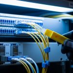
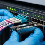
BACnet/IP and KNX IP both ride on standard Ethernet frames, but building deployments differ from campus IT in two ways: long cable distances and many small managed/unmanaged islands that must remain reachable during commissioning. In practice, you often connect building automation controllers, gateways, and supervisory switches using fiber, because fiber reduces copper surge damage risk and avoids ground potential issues across floors and risers. SFP form factor optics then become the interface contract between your switch and your building automation network.
For BACnet and KNX, the key is not just that the link comes up; it is that it stays in a known operating state. Many automation systems depend on predictable latency and minimal packet loss during polling, event subscriptions, and gateway translation. On the physical layer, that means selecting the correct wavelength, reach class, fiber type, and power level so the transceiver does not operate near sensitivity limits.
When you choose SFP modules for smart building optics, validate that the switch supports the module type (vendor compatibility list), that the module provides a digital optical monitoring interface (DOM) if you need alarm thresholds, and that the operating temperature covers the mechanical realities of building closets. In a typical equipment room, air conditioning cycles can push ambient closer to 0 to 50 C depending on insulation and enclosure airflow.
Standards and what they imply for building automation
Ethernet physical layer behavior follows IEEE 802.3 for signaling and link training, while the SFP electrical interface follows the SFP Multi-Source Agreement (MSA) from the SFP consortium. For optics performance, vendors specify parameters such as transmitter launch power, receiver sensitivity, and optical budget. For building environments, you also need to consider ANSI/TIA-568 cabling practices for fiber terminations and connector quality, because bad polishing or high insertion loss can make a link unstable even if the nominal reach looks sufficient.
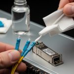
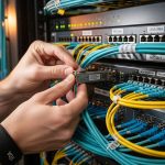
Pro Tip: In building automation closets, the most common “it worked on the bench” failure is not the transceiver; it is connector cleanliness after field termination. A single contaminated LC/SC adapter can add enough insertion loss to push the receiver into marginal operation, showing up as intermittent BACnet reads and KNX event delays long after link LEDs look stable.

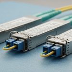
Core SFP selection: wavelength, reach, fiber type, and data rate
Start from the building’s fiber plant and the switch’s line rate. Most smart building optics deployments use 1G SFP (1000BASE-X) or 10G SFP+ depending on how many controllers and gateways share uplinks. BACnet and KNX traffic are often low bandwidth, but bursts occur during commissioning, firmware updates, and alarm storms, so uplink headroom matters.
Then map each link to a wavelength and fiber type pairing. For short-to-mid reach inside buildings, 850 nm multimode (MMF) is common, while 1310 nm single-mode (SMF) is used for longer runs between floors or across risers. Your optical budget must include not only fiber attenuation but also connector loss and splice loss; field splices frequently dominate total loss in vertical runs.
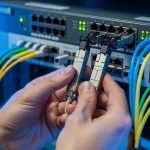
Finally, ensure the SFP module meets the switch’s electrical expectations. Many enterprise and industrial switches support specific SFP part numbers or vendor families; “works in some modes” is not acceptable for automation networks where you want consistent link training and stable optical monitoring.
Comparison table: typical SFP optics choices for building fiber
The table below compares common SFP module categories you will see when planning smart building optics for BACnet and KNX fiber backbones. Exact parameters vary by vendor and datasheet revision, so treat these as selection anchors and confirm against your switch compatibility list.
| Category | Typical wavelength | Fiber type | Target reach class | Data rate | Connector | Operating temp (typ.) | DOM availability |
|---|---|---|---|---|---|---|---|
| SFP 1000BASE-SX | 850 nm | OM2 / OM3 / OM4 MMF | ~300 m (OM3) to ~400 m (OM4) | 1G | LC | 0 to 70 C (often industrial variants lower) | Often present |
| SFP 1000BASE-LX | 1310 nm | SMF | ~10 km | 1G | LC | Often present | -40 to 85 C (common industrial options) |
| SFP+ 10G SR | 850 nm | OM3 / OM4 MMF | ~300 m (OM3) / ~400 m (OM4) | 10G | LC | -5 to 70 C (varies by vendor) | Common with DOM |
| SFP+ 10G LR | 1310 nm | SMF | ~10 km | 10G | LC | -40 to 85 C (industrial) | Common with DOM |
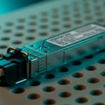
Concrete examples of vendor modules engineers recognize
In the field, teams often standardize on known part families to reduce compatibility risk. Examples include Cisco-branded optics like Cisco SFP-10G-SR, and third-party optics from vendors such as Finisar (now part of II-VI) like FTLX8571D3BCL and FS.com models like FS SFP-10GSR-85 (naming varies by catalog). The critical point is not brand loyalty; it is that the switch and transceiver behavior must match your compatibility and monitoring requirements.
For smart building optics, industrial temperature range and DOM support are often more valuable than marginal cost savings. If your automation platform requires alarm escalation when optical power falls, DOM is the difference between silent degradation and actionable maintenance tickets.

Real-world deployment: BACnet and KNX in a multi-floor building
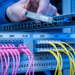
Consider a 12-floor commercial building with a 3-tier layout: edge access switches on each floor, aggregation switches in a central comms room, and a supervisory operations VLAN for NOC viewing. The building automation team deploys BACnet/IP controllers for HVAC and energy meters, plus KNX IP gateways for lighting and blinds. Each floor has 48 access ports used for controllers and gateway uplinks, with 4 uplinks per floor aggregated to a pair of switches using redundant fiber.
The cabling plan uses OM4 multimode for intra-floor cabinet runs up to 220 m and SMF for inter-floor riser segments up to 3.5 km to support future expansion. Commissioning uses SFPs with DOM so the team can verify Tx power and Rx power at install time and later during maintenance windows. In month six, a single connector adapter in one riser cabinet is replaced; DOM alarms confirm the link budget margin before users report any BACnet polling delays or KNX event latency issues.
In this scenario, the “correct” SFP is the one that matches the fiber type and reach class with at least 3 to 6 dB of margin after accounting for connector and splice loss. It also must tolerate enclosure temperature swings. For field verification, engineers record baseline Rx power readings and trend them; if the Rx power drifts too low, you schedule cleaning or re-termination before the link becomes unstable.
Decision checklist: how to choose SFPs that survive commissioning and operations
Engineers typically evaluate smart building optics with a structured checklist rather than relying on nominal reach marketing. Use the ordered steps below to reduce the chance of field failures and avoid late-stage redesign.
- Distance and reach budget: compute total link loss using fiber attenuation plus splice loss and connector insertion loss; ensure margin for aging and rework.
- Fiber type and connector standard: verify OM grade (OM2/OM3/OM4) and confirm connector type (LC vs SC) and polarity constraints for duplex fiber.
- Switch compatibility: check the exact SFP model against the switch vendor compatibility list; confirm firmware does not reject unsupported optics.
- Data rate and Ethernet mode: ensure the transceiver supports the configured speed and that auto-negotiation behavior matches the switch settings.
- DOM and monitoring requirements: decide whether you need Tx/Rx power thresholds for maintenance; validate alert behavior and polling intervals.
- Operating temperature and enclosure airflow: choose industrial-grade optics if cabinets exceed 50 C during peak cooling failure scenarios.
- Vendor lock-in risk and spares strategy: standardize part families across floors so you can keep spares on-site and avoid mixing incompatible generations.
- Optical budget verification method: plan for OTDR or at least fiber inspection plus insertion loss measurements at acceptance testing.
DOM: why it matters more than people expect
DOM support is often described as “nice to have,” but in building automation it can be operationally decisive. If you can read Rx power and optical diagnostics, you can differentiate between a failing fiber plant, an aging connector, and a switch-side issue. This reduces mean time to repair during after-hours calls when BACnet and KNX systems are expected to remain stable.
Pro Tip: If your switch supports it, poll DOM at a shorter interval during the first 48 hours after installation. Early drift patterns often reveal micro-bending, poor strain relief, or a connector that was not fully seated, before the system enters steady state.

Common mistakes and troubleshooting for smart building optics
Even experienced teams can stumble when moving from lab testing to occupied building environments. Below are concrete failure modes that show up in BACnet and KNX deployments using SFP optics, along with root causes and corrective actions.
Link comes up, but BACnet reads time out intermittently
Root cause: marginal optical budget due to excessive insertion loss from dirty connectors or damaged patch cords. Duplex polarity mistakes can also cause receiver saturation behavior that still passes basic link detection.
Solution: clean and re-seat connectors using lint-free wipes and IPA-approved methods, then verify with a fiber microscope. Measure end-to-end insertion loss and compare against the transceiver’s specified receiver sensitivity and link budget. If possible, use DOM to confirm Rx power is within the recommended operating window.
KNX event bursts cause temporary packet loss under load
Root cause: speed mismatch or incorrect switch port settings (for example, forcing 1G while the SFP negotiates differently), plus buffer stress in the access layer during event storms.
Solution: lock the port speed/duplex settings to the expected mode, confirm the SFP supports that mode, and validate VLAN tagging behavior. Review switch counters for CRC errors and late collisions; if optical errors rise, focus on physical layer optics first, not the application gateway.
SFP module rejected after a swap or returns inconsistent DOM values
Root cause: compatibility mismatch between switch firmware and transceiver EEPROM identifiers, or mixing different DOM implementations that expose different diagnostic fields.
Solution: use the switch vendor’s compatibility list and align optics part numbers across the fleet. After replacement, verify transceiver identification fields and confirm DOM thresholds are configured correctly. Keep spare optics from the same manufacturing batch if your environment is sensitive to calibration drift.
Temperature-related outages in riser closets
Root cause: transceiver operating outside temperature spec due to poor airflow, solar gain, or blocked cable trays. Some low-cost “extended” modules claim wide ranges on marketing pages but do not meet the real performance curve at high temperature.
Solution: select industrial-grade optics with verified datasheet temperature range and test in an enclosure that replicates worst-case airflow. Add monitoring for DOM and set alarms for optical power drop correlated with temperature.
Cost and ROI: balancing OEM optics, third-party SFPs, and maintenance TCO
In smart building optics projects, the optics line item is usually small compared to installation labor, commissioning time, and downtime risk. OEM SFPs often cost more upfront but can reduce compatibility failures and shorten warranty and RMA cycles. Third-party SFPs can be cost-effective, but only if you enforce switch compatibility validation and maintain a controlled spares policy.
Typical street pricing varies by speed and reach: 1G SX often falls in the lower tens of dollars per module, while 10G SR and 10G LR can be substantially higher depending on DOM support and temperature grade. The ROI decision should include expected failure rates, expected cleaning and rework labor, and the value of faster troubleshooting via DOM. If you can cut mean time to repair by even 30 to 60 minutes during after-hours incidents, the savings can exceed the delta between OEM and third-party optics within a single high-impact event.
For TCO, also consider power and cooling indirect costs. While SFP power draw differences are usually modest, reducing the number of failed optics swaps can reduce rack downtime and the associated operational disruption for building automation stakeholders.
FAQ: SFP smart building optics for BACnet and KNX
Which SFP type is most common for smart building optics in risers?
For inter-floor risers and longer SMF runs, engineers commonly use 1310 nm single-mode SFPs (1000BASE-LX or 10G LR depending on uplink speed). For intra-floor short segments on OM4, 850 nm multimode SFPs (1000BASE-SX or 10G SR) are common.
Do BACnet and KNX require DOM monitoring?
They do not require it at the protocol layer, but DOM is operationally valuable. With DOM, you can detect optical power degradation before it becomes a packet loss event that disrupts automation polling and event subscriptions.
Can I mix OEM and third-party optics in the same building?
You can, but only after validating switch compatibility and DOM behavior. Mixing part families without a compatibility plan can lead to inconsistent diagnostics, rejection behavior, or subtle differences in link stability under temperature swings.
What fiber budget margin should I plan for in commissioning?
A practical target is at least 3 to 6 dB of margin after insertion loss accounting for connectors and splices. If the building will undergo future rework, plan a slightly larger margin to absorb additional patching and cleaning cycles.
Why do I see link flaps even when OTDR looks acceptable?
OTDR can miss short, localized connector contamination or micro-bending that only affects the transceiver at certain temperatures. Combine OTDR with connector inspection, insertion loss testing, and DOM trend analysis to pinpoint the failure mode.
Where should I start if my automation traffic is unreliable after optic installation?
Start with physical layer validation: verify correct wavelength/fiber pairing, check connector cleanliness, confirm duplex/polarity, and review CRC/optical error counters. Only after physical stability is proven should you tune BACnet/KNX gateway settings or VLAN policies.
Smart building optics for BACnet and KNX succeeds when SFP selection is treated as an engineering interface contract: correct wavelength, verified reach budget, compatible switch support, and operational monitoring via DOM. Next, map your building fiber plant and switch models, then standardize optics part numbers per link class using the checklist above via smart building fiber planning.
Author bio: I have designed and commissioned fiber-based automation backbones using SFP optics in multi-floor facilities, with field verification via DOM telemetry and connector inspection workflows. I lead interoperability testing across switch firmware versions and transceiver families to minimize commissioning surprises.