If your SCADA network is still relying on copper for Modbus TCP, you already know the pain: distance limits, EMI issues, and intermittent link drops near plants and substations. This guide helps field engineers and OT integrators deploy a SCADA fiber transceiver using SFP modules so Modbus TCP traffic stays stable over long runs. You will get an implementation-style checklist, a real compatibility workflow, and the common failure modes we see in commissioning.
Prerequisites: pick the right SFP before you touch the switch
Before ordering hardware, confirm your optics and physical layer plan. For Modbus TCP over fiber, you typically need an SFP that matches the switch port type and the fiber plant (single-mode vs multi-mode), plus a link budget that covers the actual span. Also decide whether you need deterministic latency behavior; while Modbus TCP is not truly time-synchronized like some industrial protocols, jitter still matters for polling stability.
What you should have on hand
- Switch model and transceiver compatibility list (vendor “supported optics” matrix)
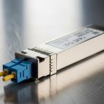
- Fiber type: SMF 9/125 or MMF 50/125, plus connector type (LC is most common for SFP)
- Estimated distance and worst-case margin (splices, patch cords, fusion loss)
- Target data rate (commonly 1G for Modbus TCP over legacy OT switches, sometimes 10G for new leaf/spine)
- Environmental constraints: ambient temperature near panels, vibration, and airflow
Reference physical layer standards
Most SFP optics for Ethernet align with IEEE Ethernet PHY behavior and optical link requirements; the Ethernet cabling and link performance expectations are rooted in IEEE 802.3 for 1G/10G interfaces. For fiber cabling practices and attenuation budgeting, installers often follow TIA guidance and vendor datasheets. Use the vendor SFP datasheet for minimum receive power, maximum transmit power, and typical wavelength (for example 1310 nm for many long-reach SMF SFPs).
Sources: [Source: IEEE 802.3] [Source: Vendor SFP datasheets]
Step-by-step implementation: Modbus TCP over fiber with an SFP
Below is a numbered, field-style workflow you can run during commissioning. The expected outcomes assume a typical OT access switch with SFP uplinks to a fiber run toward a remote RTU or IED cluster.
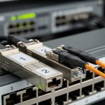
Validate switch port and optics compatibility
Confirm the exact switch SKU and port speed (for example, “SFP1G” vs “SFP+”). Then check the switch vendor compatibility list for supported SFP part numbers and whether “vendor-locked” optic IDs are enforced. In practice, we’ve seen some industrial switches accept third-party optics only if they support DOM readings and meet vendor-defined laser safety and diagnostics behavior.
Expected outcome: You know whether you need OEM optics or can use third-party SFPs safely.
Match SFP wavelength and fiber type to the plant
Pick the SFP that matches your fiber. For example, if you have MMF 50/125 and a short run inside a substation, an 850 nm MMF SFP is common. If the run is longer or you have SMF, choose 1310 nm or 1550 nm depending on the link budget and distance.
Select example SFPs that fit real Modbus TCP links
Here are representative optics you might see in deployments. Exact reach depends on optics class and power budget, so always verify with the datasheet and your measured attenuation.
| Example SFP model | Data rate | Wavelength | Typical reach | Connector | DOM | Temperature range |
|---|---|---|---|---|---|---|
| Cisco SFP-10G-SR | 10G | 850 nm | ~300 m over MMF (varies by spec) | LC | Yes (common) | Vendor-defined (often industrial/extended options) |
| Finisar FTLX8571D3BCL | 10G | 850 nm | ~300 m over MMF (varies by spec) | LC | Yes (common) | Vendor-defined |
| FS.com SFP-10GSR-85 | 10G | 850 nm | ~400 m over MMF (varies by spec) | LC | Yes (varies) | Vendor-defined |
| Generic 1GBase-SX SFP | 1G | 850 nm | ~550 m over MMF (typical) | LC | Often available | Commonly -5 to +70 C (or extended options) |
Source: [Source: Cisco SFP datasheets] [Source: Finisar/II-VI datasheets] [Source: FS.com product pages and datasheets]
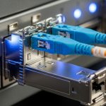
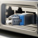
Wire the fiber correctly and verify loss
Use the correct polarity: transmit on the SFP goes to receive on the far end (LC duplex patch cords typically handle this, but polarity mistakes are common). Measure end-to-end loss using an OTDR or a fiber test kit, and include splice and patch cord loss. If the link budget is tight, clean connectors are not optional.
Expected outcome: Measured attenuation is within the optics power budget with margin.
Configure switch ports and confirm link stability
Most SFP Ethernet ports negotiate automatically. Still, confirm the port is set for the expected speed and that there are no admin mismatches (for example, disabling autoneg on one side and not the other). On the switch, verify link up and check DOM values such as laser bias current, received optical power, and temperature if available.
Pro Tip: In OT environments, link “up” can be misleading. Watch DOM receive power and error counters during the first 30 minutes after commissioning; marginal fiber cleaning issues often show up as rising CRC/FCS errors before the link fully drops.
Validate Modbus TCP traffic end-to-end
After Layer 1/2 is stable, test Modbus TCP from a SCADA master to a remote slave through the fiber link. Use a controlled poll interval and confirm round-trip time stays consistent under normal traffic. If you see timeouts, check for VLAN tagging mismatches, QoS policies, or firewall rules between OT segments.
Expected outcome: Modbus TCP reads/writes succeed with stable latency and no intermittent timeouts.


Selection criteria checklist: what engineers decide under time pressure
When you are selecting a SCADA fiber transceiver, the fastest path to reliability is a short, ordered checklist. Use it before you approve a part number for installation.
- Distance and fiber type: SMF vs MMF, measured loss, connector/splice count
- Data rate and port support: 1G vs 10G (and whether the port is SFP vs SFP+)
- Budget vs reach: include margin for aging and temperature effects
- Switch compatibility: OEM supported optics list, DOM requirements, any vendor-lock behavior
- DOM support: confirm the switch can read diagnostics (temperature, Tx bias, Rx power)
- Operating temperature: extended temperature SFP options matter in cabinets without consistent HVAC
- Vendor lock-in risk: plan for lifecycle replacement and ensure consistent optics behavior
Common pitfalls and troubleshooting: the top failure modes
Here are the issues that most often break Modbus TCP over fiber during commissioning, plus how to fix them.
Pitfall 1: Polarity and connector cleaning mistakes
Root cause: LC duplex polarity reversed (Tx-to-Tx) and/or dirty connectors causing high attenuation. Optical power may still show “some” link behavior but errors spike.
Solution: Inspect with a fiber scope, clean with approved wipes and cleaning fluid, then re-seat connectors and correct polarity using the correct duplex patch cord orientation.
Pitfall 2: Wrong SFP type for the fiber plant
Root cause: Installing 850 nm MMF optics into SMF runs (or vice versa) or selecting a reach class that cannot handle actual measured loss.
Solution: Verify fiber type in the field, confirm wavelength, and re-check link budget against measured attenuation. Replace with the correct SFP (for example, SMF 1310 nm long-reach optics when appropriate).
Pitfall 3: DOM or compatibility quirks leading to intermittent link
Root cause: Third-party optics that do not fully support DOM semantics expected by the switch, or vendor firmware that reacts to diagnostic thresholds.
Solution: Check switch logs for optic-related warnings, confirm DOM readings (Rx power in particular), and if needed, switch to OEM optics or a third-party model explicitly listed as compatible.
Cost and ROI note: what you should budget for
Pricing varies heavily by brand and temperature grade. As a practical range, many 1G SFP optics land around $30 to $150 each in typical procurement channels, while 10G optics are often $60 to $300 depending on reach and whether they are OEM vs third-party. TCO is not just the module cost: include downtime risk during commissioning, labor for re-cleaning/re-terminating fiber, and the cost of truck rolls if a marginal link causes intermittent SCADA failures.
In OT projects, OEM optics can reduce compatibility risk, while third-party optics can be fine when the switch supports them and DOM behavior matches. Either way, measured link loss and connector cleanliness usually deliver more ROI than “buying the highest advertised reach.”
FAQ: SCADA fiber transceiver questions from real buyers
Do I need a special SCADA fiber transceiver for Modbus TCP?
Not usually. You need a standard Ethernet SFP that matches your switch port and fiber type. The “SCADA” part is more about reliability practices: correct optics, stable link behavior, and monitoring for errors and DOM diagnostics.
What fiber distance can I expect with common SFPs?
It depends on MMF vs SMF and the specific optics class. Always verify using the vendor datasheet and your measured attenuation including splices and patch cords. For example, 850 nm MMF SFPs are often rated for a few hundred meters, while SMF 1310 nm optics target longer distances.
Will third-party SFPs work with industrial switches?
Sometimes, but you must check the switch compatibility list and DOM expectations. If the switch enforces specific optic IDs or reacts to diagnostic thresholds, some third-party modules can cause intermittent link behavior.
How do I confirm the fiber link is healthy beyond “link up”?
Check DOM receive power and monitor CRC/FCS error counters. Then run a Modbus TCP test with a representative poll interval for at least 15 to 30 minutes to catch marginal issues that do not fully drop the link.
What is the fastest troubleshooting path when Modbus TCP times out?
First confirm Layer 1/2: link status, optics diagnostics, and error counters. Then validate VLAN tagging, IP routing, and any OT firewall rules between SCADA master and slave endpoints.
Should I budget for spares of SCADA fiber transceivers?
Yes, especially if downtime is expensive or fiber rework is difficult. Keep at least one spare per optics type and speed, and store them in ESD-safe packaging to prevent connector contamination surprises.
If you follow the checklist above, you can deploy a reliable SCADA fiber transceiver setup for Modbus TCP without guessing on optics, polarity, or compatibility. Next step: review How to size fiber optic link budgets for OT networks so your reach and margin are based on measured loss, not marketing numbers.
.wpacs-related{margin:2.5em 0 1em;padding:0;border-top:2px solid #e5e7eb} .wpacs-related h3{margin:.8em 0 .6em;font-size:1em;font-weight:700;color:#374151;text-transform:uppercase;letter-spacing:.06em} .wpacs-related-grid{display:grid;grid-template-columns:repeat(auto-fill,minmax(200px,1fr));gap:1rem;margin:0} .wpacs-related-card{display:flex;flex-direction:column;background:#f9fafb;border:1px solid #e5e7eb;border-radius:6px;overflow:hidden;text-decoration:none;color:inherit;transition:box-shadow .15s} .wpacs-related-card:hover{box-shadow:0 2px 12px rgba(0,0,0,.1);text-decoration:none} .wpacs-related-card-img{width:100%;height:110px;object-fit:cover;background:#e5e7eb} .wpacs-related-card-img-placeholder{width:100%;height:110px;background:linear-gradient(135deg,#e5e7eb 0%,#d1d5db 100%);display:flex;align-items:center;justify-content:center;color:#9ca3af;font-size:2em} .wpacs-related-card-title{padding:.6em .75em .75em;font-size:.82em;font-weight:600;line-height:1.35;color:#1f2937} @media(max-width:480px){.wpacs-related-grid{grid-template-columns:1fr 1fr}}