A remote renewable energy site can look “simple” on paper—turbines, substations, and a few monitoring racks—but the networking transport becomes fragile when you must minimize downtime, reduce trenching, and still meet strict latency for SCADA and protection telemetry. This article is written for field engineers and network planners who are deploying fiber links at solar farms, wind projects, or hybrid substations and need a low-impact design that survives heat, dust, and harsh grounding. You will see a real deployment case, the exact transceiver and transport choices, and troubleshooting lessons learned during commissioning.

Problem and challenge: low trenching, harsh weather, and deterministic telemetry
In our case, a hybrid site combining wind turbines and battery energy storage required reliable communications between two control buildings and a central operations room. The challenge was not bandwidth alone; it was the combination of deterministic telemetry, strict maintenance windows, and a limit on new civil work. We had to avoid long open-air cable runs across service roads and reduce the number of fiber splices exposed to water ingress.
Operationally, the site carried SCADA polling, protection status, and time-sensitive alarms. Even where the application traffic was modest, engineers still care about jitter and packet loss because protection systems often rely on consistent event propagation. The transport path also had to interoperate across vendors: the core side used a DWDM-capable aggregation switch stack, while the remote side used an outdoor-capable access layer with SFP/SFP+ optics. This mix drives careful selection of wavelength, reach class, DOM behavior, and optical budget margins.
Environment specs that drove the optics and transport architecture
Before selecting optics, we measured and documented the physical and optical environment. The fiber plant included two aerial segments and one buried segment, totaling 18.6 km from the remote substation cabinet to the aggregation point. The aerial portions were exposed to wind-driven dust and temperature swings; the cabinets were rated for outdoor use but experienced internal temperatures ranging from 4 C to 58 C during commissioning week.
On the logical side, we needed to support both point-to-point links for critical telemetry and a scalable method to add sensors later without re-trenching. That pushed us toward a PON-inspired access model for low-cost expansion, but the backbone still needed DWDM-grade control for reach and channel reuse. We also had to account for grounding and surge events: the site grounding resistance and lightning protection scheme influenced how often transceivers experienced transient stress.
Key transport targets
- Backbone reach: 18.6 km single span with connector losses and splices
- Service types: SCADA, protection status, video snapshot telemetry (bursty)
- Expansion: add remote monitoring endpoints without new trenching
- Environmental limits: operational temperature down to 0 C class behavior and up to near 60 C internal cabinet temp
Chosen solution: DWDM-capable backbone plus low-impact access optics
We selected a design that minimized civil work while keeping the optical layer deterministic where it mattered. The backbone used a DWDM-capable aggregation path with a single-fiber transport strategy, and the access used pluggable optics with conservative link budgets. For short reaches within cabinets and patch trays, we used 10G SR class optics; for the 18.6 km span, we used 10G LR class optics with margin for aging and temperature.
Where we needed incremental endpoints, we adopted a PON-aligned architecture at the access edge, not as a full carrier-grade passive plant, but as a practical “tree” model that reduced additional trenching. In practice, the passive splitters were placed inside controlled enclosures rather than in open field locations. That reduced water ingress risk and kept splice points and connectorization under better environmental control.
Selected optics and why they fit renewable energy deployments
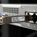
For the backbone span, we used vendor-datasheet-aligned optics such as Finisar FTLX8571D3BCL (10G LR class, LC connector) and compatible third-party 10G LR optics where DOM and temperature behavior matched. For 10G short links inside the cabinet, we used Cisco SFP-10G-SR style optics or equivalent 850 nm SR transceivers (for multimode patching). We preferred optics that provide Digital Optical Monitoring (DOM) so we could trend bias current and received power during commissioning and after seasonal temperature changes.

Specifications comparison: optics choice for wavelength, reach, power, and temperature
Because field issues often come down to optical margin and operating temperature, we compared the transceiver classes we actually used. The table below summarizes key parameters that influence link budget and compatibility: wavelength, nominal reach, connector type, DOM availability, and temperature range. Note that exact values vary by vendor and part revision, so always validate against the specific datasheet you will deploy.
| Transceiver class | Wavelength | Typical data rate | Reach class | Connector | DOM | Operating temperature (typ.) | Notes for renewable energy sites |
|---|---|---|---|---|---|---|---|
| 10G SR (850 nm) | 850 nm | 10G | ~300 m over OM3 (varies) | LC | Often available | 0 C to 70 C class (vendor dependent) | Good for in-cabinet patching; avoid long aerial multimode runs |
| 10G LR (1310 nm) | 1310 nm | 10G | ~10 km (varies) | LC | Often available | -5 C to 85 C class (vendor dependent) | Used for the 18.6 km span with conservative margins via link budget planning |
| DWDM mux/demux + pluggable optics | C-band (typ.) | 10G per wavelength channel | Extended reach (system dependent) | SC/LC (system dependent) | System monitoring dependent | Varies by chassis | Enables channel reuse and reduces fiber count; requires careful power budgeting |
For standards alignment, the Ethernet interfaces and optics behavior follow the relevant IEEE 802.3 physical layer expectations for 10GBASE-SR and 10GBASE-LR, with transceiver implementation details governed by SFP/Multi-Source Agreement style electrical interfaces. Always verify compliance with the host switch optics requirements and the transceiver identification method used by the platform.
Reference notes: IEEE 802.3 defines the optical interface behavior for 10GBASE-SR and 10GBASE-LR. IEEE 802.3 working group Additionally, check vendor DOM and SFP management behavior in the optics datasheets for real operating limits. [Source: IEEE 802.3] [Source: vendor transceiver datasheets]
Pro Tip: In outdoor renewable energy cabinets, DOM telemetry is most valuable for early detection of connector contamination and fiber micro-bending. During commissioning, log received power and bias current at least every 10 minutes for the first 2 hours after power-up, then re-check after the cabinet cycles temperature; slow drift often indicates dust or subtle insertion loss growth before you see link flaps.
Implementation steps: from link budget to commissioning under live constraints
We treated the deployment like a controlled experiment rather than a “plug and pray” rollout. Step one was building a link budget spreadsheet that included fiber attenuation, connector insertion loss, splice loss, and additional margin for temperature-induced power variation. We also accounted for aging risk: in outdoor environments, connector contamination and micro-moves during wind events can dominate the loss budget over pure fiber attenuation.
Build and validate the optical budget
- Measure or estimate fiber attenuation with OTDR where feasible; otherwise use documented reel data and verify with test results at cutover.
- Include typical connector loss (often around 0.3 dB per mated pair as a planning assumption) and splice loss (often 0.1 dB class) based on your field practice.
- Reserve margin for aging and temperature, especially for C-band DWDM paths where channel power and mux/demux insertion loss matter.
Choose optics compatible with switch DOM behavior
The host switches validated SFP identification and DOM thresholds. We cross-checked that the switch accepted the transceiver vendor ID and that DOM alarms mapped correctly to platform monitoring. Where the vendor ecosystem differed, we tested in a lab with representative firmware versions because some platforms enforce strict “DOM present” expectations.
Deploy with low-impact civil work
Instead of trenching new routes for every sensor node, we placed a sealed splitter enclosure near existing conduit runs. That reduced the number of new pull points and minimized exposed splice closures. For the backbone, we used a single-fiber approach with DWDM where channelization reduced the need for parallel fiber pulls across the same corridor.
Commission with repeatable test loops
During commissioning, we performed optical power and error-rate verification. We captured baseline receive power and verified link stability across cabinet temperature transitions. For Ethernet verification, we used traffic generators to push representative loads and monitored interface counters for CRC errors, link resets, and FEC indicators where applicable.
Measured results and lessons learned from the field
After cutover, the backbone link maintained stable throughput for telemetry and bursty monitoring traffic. Over the first 45 days, we observed no sustained packet loss events attributable to the optics layer, and link flaps dropped to near-zero after we cleaned and re-terminated two early connector sets. Received optical power drift stayed within a narrow band after we implemented strict cleaning and dust-control procedures.
Operationally, the biggest improvement came from reducing exposed splice points. By moving passive splitters and splices into controlled enclosures, we reduced moisture-related attenuation events that typically show up as intermittent degradation during rain cycles. The low-impact civil approach also cut outage windows: the team completed additional endpoint additions without new trenching, which reduced permitting and site access delays.
Common mistakes and troubleshooting tips (with root cause and fixes)
Field failures in renewable energy networking often look like “random link issues,” but they usually have repeatable causes. Below are concrete failure modes we encountered and how we corrected them.
-
Mistake: Using optics that are “spec compatible” but not DOM-behavior compatible with the host switch.
Root cause: Some platforms enforce DOM presence and threshold ranges; mismatches can trigger alarms or disable optics management features.
Solution: Validate transceiver acceptance using the exact switch firmware version; confirm DOM fields for temperature, bias, and received power match expected scaling. -
Mistake: Underestimating connector contamination during aerial-to-cabinet transitions.
Root cause: Wind-driven dust and handling at patch panels increase insertion loss; repeated connector mate cycles can trap particulates.
Solution: Implement a cleaning SOP with inspection scope checks; measure receive power before and after remating and log trend lines using DOM. -
Mistake: Oversubscribing the optical budget for DWDM without accounting for mux/demux insertion loss variation.
Root cause: Insertion loss can vary by temperature and by channel; field-installed patching can add unexpected loss.
Solution: Allocate explicit margin for mux/demux insertion and spare power headroom; verify channel power levels at commissioning and re-check after seasonal changes. -
Mistake: Ignoring temperature gradients inside outdoor cabinets when selecting “commercial” optics.
Root cause: Internal airflow patterns create hot spots; optics can run beyond their rated case temperature even if the cabinet is “rated.”
Solution: Use optics with an appropriate industrial temperature range and confirm with a calibrated thermal probe at the transceiver cage.
Cost and ROI note: realistic pricing, TCO, and failure-rate tradeoffs
In typical procurement cycles, a 10G LR SFP-class transceiver often lands in a range roughly from $80 to $250 per unit depending on OEM branding and DOM features. Third-party optics can be cheaper, sometimes $40 to $120, but field teams should budget time for compatibility validation and potential higher return rates when environmental stress is high. DWDM components (mux/demux chassis and system optics) are usually a larger upfront cost, but they reduce fiber pull quantities and permitting overhead, which can dominate total project cost for remote renewable energy sites.
ROI comes from reduced civil work, fewer truck rolls for re-splicing, and faster endpoint expansion. TCO should include cleaning consumables, inspection scopes, spares held at site, and the operational cost of downtime. In our case, the low-impact approach reduced incremental construction time for added endpoints, which shortened revenue-impacting downtime windows during staged commissioning.
Selection criteria checklist for low-impact renewable energy networking
Use this ordered checklist when selecting optics and transport choices for renewable energy sites. It is optimized for engineers balancing reach, ruggedness, and low civil impact.
- Distance and reach class: compute link budget with worst-case attenuation and connector/splice counts; do not assume nominal reach is sufficient.
- Budget and wavelength plan: choose 850 nm SR for short patching and 1310 nm LR for longer single-mode spans; for fiber-scarce corridors, evaluate DWDM channelization.
- Switch compatibility: verify SFP/SFP+ acceptance, DOM support, and vendor ID behavior for your specific switch model and firmware.
- DOM and monitoring strategy: require DOM where possible; define which alarms and thresholds your NMS will ingest.
- Operating temperature and thermal design: confirm optics case temperature and cabinet airflow; prefer industrial temperature optics for outdoor enclosures.
- Connectorization and cleaning workflow: specify LC/SC connector type and enforce inspection-based cleaning with documented SOPs.
- Vendor lock-in risk: weigh OEM optics reliability against third-party cost; run interoperability testing before scaling.
FAQ
How does renewable energy deployment differ from typical enterprise fiber?
Renewable energy sites combine outdoor exposure, frequent temperature cycling, and strict maintenance access constraints. That makes optics monitoring and connector hygiene more critical than in controlled indoor data centers. You also often have to minimize trenching, which drives architectural choices like DWDM channel reuse and localized splitters in sealed enclosures.
Can I mix OEM and third-party transceivers in the same switch stack?
It can work, but it depends on the host platform optics policy and DOM scaling expectations. Validate using the exact switch model and firmware, then monitor for link flaps and DOM alarm behavior during temperature cycling. If the platform enforces strict thresholds, mismatched optics can create noisy alarms or disable monitoring features.
What is the biggest cause of link instability after commissioning?
In outdoor renewable energy cabinets, the most common cause is connector contamination or micro-loss growth from handling and environmental dust. The second most common cause is optical budget oversubscription, especially with DWDM where mux/demux insertion loss and channel power variation can erode margin. DOM trend logs help identify both before you see persistent errors.
Is PON always the right choice for adding endpoints at renewable energy sites?
Not always. Full carrier-style PON deployments can be complex, but a PON-inspired tree model can be practical when you place splitters inside controlled enclosures and keep fiber sections protected. The decision should be based on endpoint count growth, power budget constraints, and how your transport layer integrates with SCADA and telemetry requirements.
Which standards should I reference when planning 10G links?
For Ethernet physical layer behavior, reference IEEE 802.3 for 10GBASE-SR and 10GBASE-LR expectations. Then rely on the specific transceiver datasheets and your switch vendor documentation for DOM and optical power class behavior. If you use DWDM, validate system-level channel power and insertion loss with the DWDM vendor’s planning guide. [Source: IEEE 802.3] ITU-T G.652 fiber guidance
What should be included in an acceptance test for field-installed optics?
Include baseline transmit/receive power checks, interface error counters, and a short traffic stress test. Then repeat at least one test after temperature stabilization in the cabinet to catch thermal drift issues. If you have DOM, export telemetry logs and confirm your NMS thresholds match the optics behavior.
Renewable energy networking succeeds when optics selection is backed by measured link budgets, strict connector hygiene, and architecture choices that reduce trenching and exposed splice points. If you are planning the next phase of low-impact expansion, review low-impact fiber design to align civil constraints with DWDM and access-layer transport decisions.
Author bio: I am a telecom engineer who has designed and commissioned DWDM and 5G fronthaul/backhaul fiber transport for outdoor energy sites, focusing on link budget discipline and operational monitoring. I have deployed SFP and SFP+ optics in rugged cabinets and used DOM telemetry to reduce recurring field faults.