You can have a strong QKD fiber optic system design on paper and still fail in the field due to transceiver optics mismatches, connector loss, DOM misreads, or thermal drift. This guide helps network and optical engineers select and validate the transceiver layer so your quantum key exchange stays stable under real plant conditions. It focuses on operational compatibility, measurable link budget inputs, and the failure modes that most often trigger intermittent key exchange outages.
Where the transceiver fits in a QKD fiber optic link
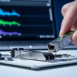
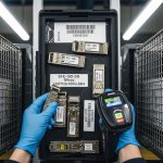
In most deployments, the QKD appliance couples into standard fiber infrastructure using an optical transceiver (SFP/QSFP class or vendor-specific pluggables) plus optical filtering and isolation stages inside the QKD head. The transceiver’s job is to present the expected wavelength, optical power range, extinction ratio, and spectral characteristics to the QKD receiver chain. QKD systems also tend to be more sensitive to polarization effects, reflection noise, and excess loss than conventional data links, so “works at 10 km” is not the same as “maintains secure key rate.”
Practically, engineers treat the transceiver as a constrained optical interface: you must meet the QKD vendor’s wavelength plan and power budget, and you must avoid optical return loss and connector contamination that can couple into the quantum channel. For classical co-propagation (same fiber carrying data), the transceiver also influences crosstalk and isolation requirements. If you are using standard transceiver form factors, verify that the QKD vendor explicitly supports that class and that the optics meet the required spectral width and out-of-band attenuation.
What to verify in the QKD appliance documentation
- Supported wavelengths (commonly around 1310 nm for many fiber quantum experiments, and 1550 nm in other vendor designs; use your vendor’s exact band plan).
- Launch power window accepted by the QKD receiver optics and safety interlocks.
- Optical return loss expectations (often tighter than typical Ethernet optics).
- Polarization handling requirements: does the system use polarization diversity, and what does it expect from the transceiver path?
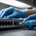
- Connector type and cleaning requirements: APC vs UPC can change back-reflection behavior.
Transceiver spec comparison: the parameters that actually drive QKD stability
Conventional Ethernet optics check link reach and bitrate. QKD fiber optic links additionally depend on spectral purity, power control, and optical interface behavior. Use the table below as a field checklist for the most relevant parameters when comparing pluggables and vendor-supported optics.

| Parameter | What QKD cares about | Typical Ethernet-class guidance | What to request from vendor |
|---|---|---|---|
| Wavelength (nm) | Receiver filter alignment and quantum channel compatibility | 1310 nm or 1550 nm families | Exact band and center tolerance |
| Reach / link budget | Secure key rate depends on received photon statistics | Specified by vendor for classical data | QKD-specific loss budget and acceptable margin |
| Transmit power range (dBm) | Too high can trigger safety limits; too low reduces key rate | Varies by module class | Allowed launch window and feedback behavior |
| Spectral width | Out-of-band coupling can raise noise in the quantum receiver | Measured for data link spectral compliance | Laser linewidth and side-mode suppression expectations |
| Connector / return loss | Back-reflections can create spurious counts or impair filtering | UPC is common; QKD may require APC | Return loss target and connector type requirement |
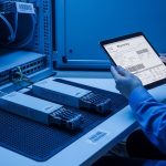
| DOM / diagnostics | Enables proactive detection of drift and aging | Compliant with industry MDIO/I2C patterns | DOM mapping and interpretation for QKD alarms |
| Temperature range | Thermal drift changes power and wavelength | Commercial or industrial | Operating class and derating guidance |
| Form factor | Mechanical fit and optical path assumptions | SFP/SFP+/QSFP28 common | Explicit compatibility list |
When selecting a QKD fiber optic transceiver, treat the transceiver’s optical power control loop as part of your system. Many pluggables implement automatic power control, but they may behave differently under varying ambient temperature and aging. Field teams often observe key exchange instability after a swap because the new module’s power leveling and spectral characteristics differ slightly, even if the data link comes up immediately.
Selection checklist: how to pick optics for secure key exchange uptime
Use this ordered decision checklist. If you can’t validate an item with a measurement plan, do not assume the QKD system will behave like a standard Ethernet link.
- Distance and loss budget: compute fiber attenuation at the QKD wavelength plus connector and splice loss. Add a margin for aging and seasonal temperature changes.
- QKD vendor wavelength plan: match the exact band and ensure the transceiver is in the vendor’s supported optics list.
- Launch power window: confirm the module can be operated within the QKD appliance’s accepted transmit range. Ask for acceptable dBm at the QKD input, not just module nominal.
- Compatibility with switch or host optics: if you are using an intermediate transceiver host, confirm that the host supports the module type (SFP vs SFP+ vs QSFP) and that electrical signaling expectations match.
- DOM and alarm thresholds: verify which parameters the QKD controller reads (temperature, bias current, received power) and how it reacts to thresholds.
- Operating temperature and derating: choose industrial or extended modules if the QKD rack experiences hot spots. Use vendor derating curves where available.
- Optics safety and reflection behavior: confirm connector type (APC if required), and ensure the installation meets cleaning and inspection standards.
- Vendor lock-in risk: evaluate third-party optics only if the vendor provides explicit compatibility. Otherwise, plan for higher replacement cost and faster RMA cycles.
Concrete validation steps before cutover
- Measure end-to-end loss with an OTDR and confirm splice/connector contributors. Record values in dB with event locations.
- Confirm optical power at the QKD input using a calibrated optical power meter and the correct wavelength filter.
- Run a stabilization window: monitor key rate and QBER-like metrics (if provided by the appliance UI) for at least 1 to 4 hours after warm-up.
- Log DOM readings every minute (or per appliance interval) and correlate with any key rate drops.

Pro Tip: In many field incidents, the data link remains stable while QKD key exchange intermittently fails because the transceiver swap changed spectral width or return-loss behavior. Treat connector cleanliness and spectral compliance as first-class variables, and always validate with a key-rate stabilization test, not just link-up status.
Real-world deployment scenario: leaf-spine with classical co-propagation
Consider a 3-tier data center leaf-spine topology where 48-port 10G ToR switches uplink to spine switches using 10G SR optics over OM3/OM4. The security team overlays a QKD fiber optic link between two critical pods, using the same fiber corridor but separating quantum and classical paths via wavelength-division multiplexing inside the QKD rack. In this environment, engineers typically budget 0.5 dB connector loss per end and 0.2 dB splice loss, then allocate an additional margin for patch panel wear. After installing a replacement transceiver, the classical 10G link can still pass traffic instantly, yet the QKD key rate drops for hours because the new module’s launch power sits near the edge of the QKD appliance acceptance window.
To prevent that, teams measure launch power at the QKD input and verify it stays within the vendor’s allowed dBm range across temperature. They also inspect APC connectors under magnification and clean them using lint-free wipes and approved solvent or cleaning cassettes. Once the transceiver is tuned to the correct operating window, key exchange resumes and remains stable through a full thermal cycle in the rack.
Common mistakes and troubleshooting for QKD fiber optic transceivers
Below are failure modes seen in production environments. Each includes the root cause and a practical fix.
-
Mistake: Installing a third-party transceiver that matches wavelength and reach but is not in the QKD vendor’s compatibility list.
Root cause: DOM mapping, laser spectral characteristics, and power-control behavior differ; QKD receiver noise filtering expects a specific spectral footprint.
Fix: Validate using the QKD vendor’s supported optics list or request a compatibility letter. Run a stabilization test while logging key rate and DOM temperature/bias/current. -
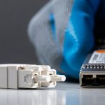
Mistake: Using UPC connectors where the QKD design expects APC (or vice versa).
Root cause: Back-reflections change the effective noise floor and can trigger spurious detection events.
Fix: Re-terminate or re-patch with the correct connector type, then inspect with a fiber microscope and clean both ends before reconnecting. -
Mistake: Assuming “module passes link-up” means “optics are within QKD power window.”
Root cause: The QKD appliance may clamp or attenuate differently than a standard host; module nominal power can drift with temperature.
Fix: Measure optical power at the QKD input and confirm it tracks within the allowed range during warm-up and after rack temperature changes. -
Mistake: Neglecting DOM alarms and replacing modules without correlation.
Root cause: Thermal cycling and aging can push bias current or received power outside thresholds, but the controller alarms may be overlooked.
Fix: Collect DOM logs and correlate with key rate drops; replace only after you confirm the failing parameter (e.g., rising temperature or falling received power).

Cost and ROI note: balancing OEM confidence vs TCO
Pricing for QKD fiber optic transceivers varies widely based on wavelength band, form factor, and whether they are OEM-branded or certified third-party. In practice, OEM optics for specialized QKD-compatible wavelengths can cost roughly $250 to $900 per module, while certified third-party modules may land around $120 to $600. The ROI is not only about purchase price: it is about reducing downtime and avoiding repeated RMA cycles caused by compatibility gaps.
TCO drivers include: installation labor, optical test equipment usage, expected failure rates, and the time required to restore key exchange. If your QKD system supports DOM-based health monitoring, you can lower mean time to repair by detecting drift before a full outage. Conversely, if you rely on non-supported optics, you may spend more on labor and downtime than you save on unit cost.
FAQ
What makes a transceiver “QKD-compatible” versus just Ethernet-compatible?
QKD-compatible optics must meet the QKD appliance’s wavelength plan, power window, and spectral/return-loss expectations. Even if Ethernet link-up succeeds, spectral width and back-reflection behavior can still raise quantum channel noise. Always validate with the QKD vendor’s supported optics guidance and a key-rate stabilization test. Source: IEEE 802.3
Can I use the same fiber for classical data and QKD with one transceiver?
Usually you separate quantum and classical paths using isolation and wavelength separation inside the QKD rack, not by using a single transceiver for both channels at the same wavelength. The transceiver choice still affects noise coupling and received power at the quantum receiver. Confirm co-propagation architecture with your QKD vendor and measure insertion loss and crosstalk budgets.
How do DOM readings help day-to-day QKD operations?
DOM provides temperature, bias current, transmit power, and sometimes received power, which helps you correlate key rate drops with optical drift. Engineers use these logs to predict aging and to decide whether to clean connectors or replace the transceiver. The key is aligning DOM thresholds with the QKD controller’s alarms and using consistent logging intervals.
What is the most common root cause of intermittent key exchange after a optics swap?
The most common causes are connector reflection issues (wrong connector type or contamination) and launch power mismatch (module power leveling differs from what the QKD chain expects). Less frequently, spectral characteristics differ enough to change the quantum receiver noise floor. Troubleshoot by measuring optical power at the QKD input and inspecting connectors before assuming a defective module.
Do I need industrial temperature range optics for typical data centers?
If your QKD rack runs near the upper end of its thermal envelope or has hot spots, industrial or extended temperature optics can reduce drift-induced outages. If you operate within the module’s rated range and maintain airflow, commercial optics may be acceptable. The decision should be based on measured ambient temperature and documented derating curves from the module datasheet.
Are there standards specifically for QKD transceivers?
There is no single “QKD transceiver standard” equivalent to Ethernet optics specifications; QKD systems are vendor-specific in optical filtering, power control, and receiver timing. You still benefit from general optical best practices and fiber standards, but the decisive acceptance criteria come from the QKD appliance documentation. For classical transport interoperability, IEEE 802.3 remains relevant to electrical and optical interface expectations. Source: TIA
QKD fiber optic reliability hinges on transceiver wavelength alignment, power window control, connector return-loss behavior, and validation using real key-rate stabilization—not just link-up. Next, map your current link budget and connector plan using QKD link budget and optical loss budgeting.
Author bio: Field engineer focused on optical transport and secure networking deployments, with hands-on experience validating transceiver compatibility using DOM logs and calibrated power measurements. I write implementation guides that translate vendor optics constraints into measurable acceptance criteria.