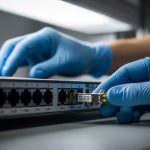
When your edge site is a converted closet, a roadside cabinet, or a snowy remote warehouse, the transceiver choice becomes a reliability decision, not an afterthought. This article helps network engineers and field techs select edge computing transceivers that actually survive optics budget limits, switch compatibility quirks, and temperature swings. You will get practical selection checklists, spec comparisons, and troubleshooting patterns pulled from real link bring-up work.

Why edge computing transceivers fail in the field (and how to prevent it)
In central data centers, you often have spare optics, stable power, and predictable cooling. At the edge, you get long patch runs, mixed fiber cleanliness, vibration, and sometimes borderline ambient temperatures. Most link issues boil down to optics mismatch (wrong wavelength or fiber type), insufficient optical power margin, or switch-side constraints like DOM handling and vendor-specific quirks. The fix is usually straightforward once you treat the transceiver like an engineered component with an explicit link budget and compatibility plan.
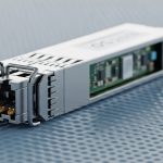
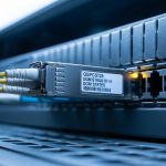
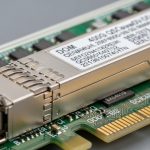
Edge computing transceivers are typically SFP/SFP+/SFP28, QSFP+/QSFP28, or newer small form-factor optics depending on the NIC and switch ports. For fiber, engineers commonly target 10G over multimode (OM3/OM4) at 850 nm or 10G over single-mode (OS2) at 1310 nm, plus higher-speed variants like 25G/50G/100G depending on the platform. The IEEE 802.3 standards define signaling and electrical requirements, but vendors still differ in DOM behavior, laser safety implementations, and supported transceiver lists.
For authoritative baseline behaviors, use IEEE Ethernet optics references such as IEEE 802.3ae (10GBASE), IEEE 802.3ba (40G/100G), and platform vendor transceiver compatibility guides. For transceiver physical and optical interfaces, also cross-check with vendor datasheets and the relevant ANSI/TIA cabling guidance. References: IEEE 802.3ae, IEEE 802.3ba, ANSI/TIA cabling standards
Core specs that matter: wavelength, reach, DOM, and optical power
When I bring up edge links, I write down the exact optics parameters from both sides: wavelength, reach rating, transmit power, receiver sensitivity, and connector type. Then I compare those with a real link budget using your measured fiber loss (including patch cords, splices, and connector insertion loss). This is where many teams skip steps and end up with intermittent link flaps after a fiber remap or a cleaning failure.
Below is a practical comparison of common transceiver types you will see in edge deployments. Values vary by vendor model, so treat them as typical ranges and confirm against the specific datasheet or SFF module label before ordering. Also note that operating temperature and DOM features can be the difference between “works in the lab” and “works during winter field ops.”
| Transceiver type | Typical data rate | Wavelength | Typical reach (rated) | Fiber type | Connector | DOM support | Operating temperature |
|---|---|---|---|---|---|---|---|
| SFP+ SR (10GBASE-SR) | 10G | 850 nm | 300 m (OM3) / 400 m (OM4) | OM3/OM4 multimode | LC | Usually supported | Often 0 to 70 C (some extend) |
| SFP+ LR (10GBASE-LR) | 10G | 1310 nm | 10 km | OS2 single-mode | LC | Usually supported | Often 0 to 70 C (some extend) |
| QSFP28 SR (25GBASE-SR) | 25G | 850 nm | 70 m (OM3) / 100 m (OM4) | OM3/OM4 multimode | LC | Usually supported | Often 0 to 70 C (some extend) |
| QSFP28 CWDM/DR (platform-dependent) | 25G/40G/100G variants | ~1270-1610 nm bands | 1-10+ km (varies) | OS2 single-mode | LC | Often supported | Varies by model |
Real examples you can map to this table include vendor and brand families like Cisco SFP-10G-SR, Finisar FTLX8571D3BCL (10G SR class optics), and FS.com optics such as SFP-10GSR-85. Exact power and sensitivity numbers differ by exact part number, but the selection logic stays the same: pick the correct wavelength for the fiber, verify the link budget, and ensure temperature class matches your edge enclosure realities. References: Cisco transceiver documentation, Finisar/II-VI optics datasheets, FS.com optics catalog
Pro Tip: If your edge site uses patch panels or field-terminated connectors, add a deliberate “cleaning buffer” to your optical margin. A single dirty LC connector can create enough penalty to turn a marginal link into an intermittent one, especially after temperature cycling and dust settling.

Deployment scenario: 10G fiber to a retail edge site with real constraints
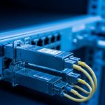
One deployment I supported was a 3-tier topology: a regional aggregation switch feeding multiple retail edge gateways using 10G uplinks. Each retail site had a single fiber run of 2.8 km from the building demarc to the edge gateway, with six LC connections across patch panels and four fusion splices. The measured fiber attenuation was about 0.35 dB/km for OS2, and we logged total connector loss at roughly 0.5 dB per mated pair after cleaning verification. With an OS2 1310 nm optics class (10G LR style), we had enough margin for normal aging, but we still scheduled connector cleaning at commissioning and after any fiber rework.
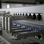
On the switches, we enforced compatibility by using transceivers that match the platform’s supported transceiver list and confirmed DOM reporting works with the management plane. Where we used third-party modules, we validated that the switch accepted them without “DOM mismatch” alarms and that the reported temperature/laser bias stayed within thresholds. After go-live, the only recurring incident was not the optics itself: a fiber remap swapped one OS2 jumper into an adjacent multimode trunk, causing a full link drop until we corrected the fiber label and verified wavelength behavior. This is why you should treat fiber labeling and transceiver wavelength as a paired configuration, not independent steps.
Selection checklist engineers actually use for edge computing transceivers
Here is the ordered decision list I’ve seen work best during field bring-up. The goal is to avoid “it probably works” purchasing and instead lock down the parameters that determine link stability.
- Distance and fiber type: Confirm OS2 vs OM3/OM4, end-to-end run length, and number of connectors/splices. If you do not know the fiber type, verify with test documentation before ordering.
- Wavelength alignment: Match 850 nm optics to multimode and 1310/1550 nm optics to single-mode based on your planned reach.
- Optical power margin: Use vendor transmit power and receiver sensitivity from the datasheet, then add measured fiber attenuation plus connector/splice penalties. Keep margin for cleaning, repairs, and aging.
- Switch compatibility: Check the switch vendor’s transceiver compatibility list, especially for SFP/SFP+/QSFP28 platforms that enforce DOM or threshold behavior. Validate DOM reading in a staging environment.
- DOM and monitoring: Confirm the module supports standard digital optical monitoring and that the switch queries it correctly. Ensure telemetry fields you rely on (temp, bias, power) are present.
- Operating temperature and enclosure reality: Edge sites can exceed “normal” 0 to 70 C assumptions. Choose extended temperature optics when the cabinet sees high sun loading or near-freezing conditions.
- Vendor lock-in risk: Weigh OEM vs third-party. Third-party can reduce cost, but plan for compatibility testing and occasional RMA handling differences.
- Connector cleanliness and field serviceability: LC dust caps, cleaning kits, and labeling discipline are part of the transceiver solution. Plan maintenance intervals.

Common mistakes and troubleshooting patterns at the edge
Edge failures are usually predictable once you know the failure modes. Here are the most common mistakes I see, with root causes and fixes you can apply quickly.
Wrong fiber type or remapped jumper (symptom: dead link, no light)
Root cause: OS2 single-mode optics installed on a multimode fiber (or vice versa), often after a patch panel remap. Even if the physical connector matches, the modal behavior and wavelength coupling can prevent the receiver from locking.
Solution: Verify fiber type using documentation or OTDR/test results, then confirm the transceiver wavelength and ensure the jumper is in the correct trunk. After corrections, clean connectors and run a link validation test from the switch CLI.
Insufficient optical budget (symptom: link flaps under temperature changes)
Root cause: Your measured loss plus connector penalties leaves little margin. Temperature cycling affects laser output and receiver sensitivity slightly, pushing the link over the edge when the optics aging or connector contamination increases.
Solution: Recalculate the link budget using datasheet transmit/receive values and measured attenuation. If you are near the margin, reduce insertion loss (shorten patch cords, remove unnecessary splices), clean connectors, or move to a higher-reach optics class appropriate for your fiber type (still within IEEE 802.3 requirements and platform constraints).
DOM/threshold mismatch alarms (symptom: port errors or “unsupported transceiver” warnings)
Root cause: Some platforms enforce certain DOM expectations, including how thresholds are reported or how the module responds to queries. Non-compatible third-party optics may still light fiber but trigger management alarms or limit link stability.
Solution: Test the exact transceiver SKU with the target switch model in staging. Prefer modules with documented DOM support and confirm the switch accepts them without warnings. If you must use third-party, buy from a vendor that provides clear compatibility notes and supports RMA.
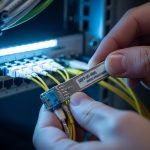
Dirty LC connectors and no fiber inspection (symptom: receive light present but high BER)
Root cause: Dust or micro-scratches on LC endfaces raise insertion loss and can increase bit error rate, especially after outdoor cabinet servicing where airborne dust is common.
Solution: Use a fiber inspection scope, clean with proper wipes and alcohol or approved cleaning methods, and recheck link quality counters. Keep dust caps on every unused port and enforce a cleaning step after any disconnection.
Cost and ROI: when third-party makes sense and when it does not
Edge computing transceivers usually represent a small part of the overall site cost, but they can dominate downtime risk. In general, OEM optics might cost roughly 1.5x to 3x compared to compatible third-party modules, depending on speed and reach. For example, a basic 10G SR SFP+ module may be relatively affordable, while extended-temperature and higher-speed optics can be significantly more expensive.
TCO is not just purchase price. Add shipping, spares inventory, and labor time for troubleshooting and cleaning. If your edge environment is harsh (outdoor cabinets, high vibration, frequent maintenance windows), the ROI of higher-quality optics and better compatibility testing can be strong because it reduces repeat visits. Conversely, if you have controlled enclosures and solid fiber documentation, third-party optics with confirmed DOM behavior can deliver good cost savings with manageable risk.
When estimating failure impact, include the operational cost of downtime, not just RMA shipping. In many real cases, the true cost comes from truck rolls, weekend dispatches, and service restoration time.
FAQ
What data rates are most common for edge computing transceivers?
In many practical edge deployments, 10G (SFP+ or QSFP+) and 25G (SFP28/QSFP28) show up most often due to switch and NIC availability. Some networks move directly to 40G or 100G for aggregation, but the selection process is the same: verify fiber type, reach, and platform compatibility.
How do I confirm my edge fiber link budget before ordering optics?
Start with end-to-end distance, then add measured fiber attenuation plus estimated connector and splice loss. Pull transmit power and receiver sensitivity from the exact transceiver datasheet, then ensure you keep a margin for cleaning and aging. If you cannot measure loss reliably, at least validate with OTDR and connector inspection before you finalize the optics choice.
Will third-party edge computing transceivers work on managed switches?
Often yes, but not always. Your biggest compatibility risks are DOM behavior, supported transceiver lists, and threshold reporting. Best practice is to test the exact SKU with the exact switch model and validate link stability and telemetry in staging.
Do I need extended-temperature optics for outdoor edge cabinets?
If the cabinet sees direct sun, winter cold, or poorly controlled airflow, extended-temperature optics are often worth it. Check the module’s operating temperature range in the datasheet and compare it to your site’s worst-case ambient conditions. If you ignore this, you can get intermittent link loss that looks like “random” failures.
What is the fastest way to troubleshoot a dead edge fiber link?
Confirm wavelength and fiber type first, then inspect and clean connectors. Next, check switch port counters and DOM telemetry (if supported) to see whether the receiver is getting signal and whether laser bias/power are within thresholds. Finally, verify the jumper mapping at the patch panel and retest.
Which standards should I reference during transceiver selection?
Use IEEE 802.3 for Ethernet physical layer requirements (for example, 10GBASE and 40G/100G families). For cabling and installation practices, also refer to ANSI/TIA guidance and vendor transceiver datasheets. Standards help you avoid electrical and optical mismatch, but platform compatibility guidance still matters for real deployments.
If you want fewer surprises at deployment day, treat edge computing transceivers as part of an engineered optical link: validate fiber type, compute margin, and test DOM and compatibility with your specific switch model. Next, review how to plan fiber cleaning and inspection for edge networks to reduce the most common real-world downtime trigger: dirty connectors and mis-mapped jumpers.
Author bio: I build and troubleshoot edge fiber links in the real world, from indoor cabinets to outdoor roadside enclosures, and I keep a running log of which optics and switch combos behave consistently. I also maintain field checklists for DOM telemetry, optical budgets, and connector cleaning workflows across mixed vendor gear.