If you operate an OTN transport network, the optics choice for a G.709 fiber module can be the difference between clean commissioning and weeks of link flaps. This article helps network architects, transport engineers, and IT directors compare OTU1, OTU2, and OTU4 transceiver options—covering performance tradeoffs, compatibility realities, and budget-driven ROI. You will get a decision checklist, a troubleshooting playbook, and a clear recommendation for which option fits your use case.
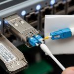
[[IMAGE:A high-resolution macro photography scene of a pluggable optical transceiver module on an anti-static mat, connectors and laser aperture visible, neutral lab lighting, shallow depth of field, realistic reflections, product labels blurred for privacy, 50mm lens look, ultra-detailed texture]
OTU1 vs OTU2 vs OTU4: What changes inside the transport layer
OTN framing defined by ITU-T G.709 maps client traffic into OTU containers with different payload sizes, overhead structures, and typical line rates. In practice, your G.709 fiber module selection is driven by which OTU you terminate (OTU1, OTU2, or OTU4) and what optical interface your line system expects. OTU1 is commonly associated with lower-capacity transport, while OTU2 and OTU4 scale up throughput and typically align with higher-speed optics and stricter system budgets.
When vendors talk about “OTU1/OTU2/OTU4 optics,” they usually mean the transceiver is provisioned for the corresponding electrical line interface and OTN framing mode. That affects signal encoding, FEC behavior, and how the receiver handles power and dispersion. Even if two modules share the same wavelength family (for example, 1310 nm or 1550 nm), they are not always interchangeable because the host expects a specific OTU rate and interface profile.
Practical implication for engineers
Before buying, confirm the exact interface your OTN mux/demux, ROADM, or packet-optical platform uses. The same chassis might support multiple OTU types, but firmware and optics inventory must match. Field experience shows that “it fits mechanically” is not the same as “it will lock and pass OTU alarms.” Always validate the OTU mode in the transceiver DOM and on the host provisioning screens.
Head-to-head optics comparison: reach, wavelength, power, and operating limits
The biggest operational differences between OTU1, OTU2, and OTU4 transceivers show up in link budget, optical power classes, and temperature qualification. In real deployments, you do not just pick based on nominal reach; you pick based on your fiber characteristics, connector losses, and margin for aging splices. The table below compares representative transceiver parameters for common single-mode deployments; always verify exact specs in the vendor datasheet for your exact part number.
| Parameter | Typical OTU1 G.709 module | Typical OTU2 G.709 module | Typical OTU4 G.709 module |
|---|---|---|---|
| OTU mode | OTU1 | OTU2 | OTU4 |
| Common wavelength options | 1310 nm or 1550 nm bands (varies) | 1550 nm band (varies) | 1550 nm band (varies) |
| Data rate class (line) | Lower than OTU2/OTU4 | Higher than OTU1 | Highest among the three |
| Reach class on SMF | Often tens of km (system dependent) | Often tens of km with more margin control | Often tens of km with tight budgets |
| Connector type | LC duplex (common) | LC duplex (common) | LC duplex (common) |
| DOM support | Frequently yes (I2C, SFF-8472/industry DOM) | Frequently yes | Frequently yes |
| Optical Tx power (class) | Moderate transmit power | Higher or tighter min/max window | Tighter optical power window |
| Receiver sensitivity (class) | Moderate sensitivity | Improved sensitivity but stricter alignment | Stricter sensitivity and dispersion tolerance |
| Operating temperature | Industrial or extended | Industrial or extended | Industrial or extended |
Why keep it “typical” rather than exact? Because OTU optics are sold as complete line-system components: the electrical interface, the optical front-end, and the host provisioning all matter. For example, a third-party module may advertise “OTU2 compatible,” but the host might require a specific FEC or OTN framing profile. For authoritative baseline requirements, reference ITU-T recommendations and vendor datasheets. [Source: ITU-T G.709], [Source: IEEE 802.3] for general optical interface context, and [Source: vendor transceiver datasheets] for the actual link budget and DOM tables.
[[IMAGE:Clean vector illustration comparing three stacked OTN waveforms labeled OTU1, OTU2, OTU4, with arrows showing overhead and payload mapping, flat design, high contrast blue and orange palette, white background, crisp typography]
Pro Tip: In the field, OTU “compatibility” failures often trace back to provisioning mismatches rather than optical budget. Before you swap fibers, confirm the host is set to the correct OTU mode and that the transceiver DOM reports the expected rate profile; many platforms will bring up a port electrically but never reach OTU lock.

Cost and ROI: Why OTU4 optics can be cheaper per bit yet riskier per link
From a budgeting perspective, OTU4 optics can look attractive because they deliver higher capacity per transceiver. However, the total cost of ownership (TCO) depends on installed spares, commissioning time, and the probability of repeat truck rolls if the link does not meet the system margin. In many operations centers, the “hidden” ROI is the reduction in downtime during upgrades and the ability to reuse existing fiber plant without aggressive re-termination.
Typical street prices vary widely by OEM versus third-party sourcing and by qualification level. As an order-of-magnitude reference, OEM optics for transport platforms can range from roughly $800 to $3,000+ per module depending on OTU type and reach, while qualified third-party modules are often lower but require strict compatibility validation. TCO drivers include warranty terms, return handling, expected failure rates over temperature cycling, and how well the optics integrate with your monitoring tooling.
TCO checklist that IT directors will recognize
- Installed spare strategy: If OTU4 links are critical, ensure you stock the right OTU mode spares, not just “same wavelength” spares.
- Power and cooling impact: Higher-performance modules may draw more power; validate against your equipment’s thermal margin.
- Commissioning labor: A module that requires repeated adjustments can erase optical savings quickly.
- Vendor lock-in risk: If only one vendor’s optics reliably lock, your procurement flexibility decreases.
Compatibility and governance: How to avoid “it works in one chassis” surprises
Enterprise architecture governance matters in transport networks because optics are both a physical component and a software-defined interface profile. A robust governance approach treats optics like controlled configuration items: each approved part number is mapped to a specific host model, firmware version, OTU mode, and wavelength band. This is especially important when you use mixed vendor optics to manage procurement cost.
At the protocol level, OTN framing is defined by ITU-T G.709, but the host’s implementation determines whether it expects certain alignment, FEC settings, and alarm thresholds. At the electrical/physical layer, pluggables often follow industry mechanical standards; DOM behavior commonly relies on I2C access patterns and standardized register sets. Still, you cannot assume that “DOM present” implies “DOM interpreted correctly by your platform.”
Governance steps that reduce risk
- Build an optics compatibility matrix: Host model, firmware baseline, OTU mode, wavelength, connector type, and approved part numbers.
- Require DOM validation: Confirm key DOM fields (temperature, Tx bias/current, Tx power, Rx power) appear and match expected ranges.
- Mandate a link bring-up test: Record OTU lock time, alarm state transitions, and BER performance if available.
- Document acceptance criteria: Define minimum optical power levels and maximum allowed alarms for commissioning sign-off.
Selection criteria: an engineer-ready decision checklist for OTU1/OTU2/OTU4
When you are selecting a G.709 fiber module, the fastest path to success is to evaluate distance, optics budget, and host compatibility together. The checklist below reflects how field engineers actually prevent rework.
- Distance and link budget: Verify fiber attenuation, connector loss, splice loss, and any patch panel penalties; ensure you have margin for aging.
- OTU mode requirement: Choose a module explicitly provisioned for OTU1, OTU2, or OTU4; do not rely on wavelength alone.
- Switch or platform compatibility: Confirm the host line card supports that OTU rate profile with that transceiver type.
- DOM and monitoring support: Ensure your NOC tooling can read DOM and that thresholds align with your alerting model.
- Operating temperature range: Match your environment: front-to-back airflow patterns can create hotspots.
- Fiber type and dispersion considerations: Confirm single-mode grade and ensure dispersion tolerance fits the system design.
- Vendor lock-in risk: Evaluate whether you can source alternates without risking bring-up failures.
- Warranty and RMA process: For transport links, turnaround time matters as much as price.

Common mistakes and troubleshooting tips that save hours
Even experienced teams run into predictable failure modes. Below are concrete pitfalls with root causes and fixes based on common OTN optical commissioning patterns.
“Same wavelength, different OTU mode” mismatch
Root cause: The module is physically compatible but the host is configured for a different OTU rate (or the transceiver profile does not match the expected electrical framing). The link may show optical receive light but never reaches OTU lock.
Solution: Confirm OTU mode configuration in the host, read DOM-provided rate profile if available, and swap to a module explicitly specified for the correct OTU mode.
Marginal power budget from patch panel losses
Root cause: The link budget assumed “direct fiber,” but the real path includes patch cables, dirty connectors, and additional splices. OTU4 is often less forgiving because system margins can be tighter.
Solution: Clean and inspect connectors with a fiber scope, re-terminate if needed, and re-measure received power at the far end. Use spare jumpers to isolate whether the loss is in the patching or in the fiber run.
DOM reads but monitoring thresholds are wrong
Root cause: DOM values may exist, yet your monitoring system maps registers incorrectly for that vendor’s transceiver profile. You end up chasing false alarms or missing real degradation.
Solution: Update monitoring mappings for the approved transceiver part number and validate alerts during commissioning. Correlate DOM trends with known-good baselines.
Thermal hotspot causes intermittent link instability
Root cause: The module operates above its specified temperature range due to airflow blockage, mis-seated fans, or restricted front-to-back cooling paths.
Solution: Check chassis thermal telemetry, verify fan RPM and filter status, and confirm that the module’s temperature stays within datasheet limits during peak load.
Decision matrix: which option fits your architecture constraints
Use this matrix to align OTU selection with operational realities. It is a governance-friendly view that combines performance intent with procurement and risk.
| Reader profile | Best fit OTU mode | Why | Main watch-outs |
|---|---|---|---|
| Cost-conscious, shorter reach | OTU1 | Lower capacity per channel, simpler budget assumptions | Confirm platform OTU1 support and DOM mapping |
| Balanced capacity upgrade | OTU2 | More throughput with manageable complexity | Validate system margin and dispersion tolerance |
| High-capacity backbone or constrained fiber routes | OTU4 | Highest capacity per channel; efficient when fiber plant is limited | Tighter link budgets, stricter compatibility, higher commissioning rigor |
| Mixed-vendor procurement strategy | OTU1 or OTU2 | More options often exist, easier qualification | Governance matrix and bring-up testing are mandatory |
| Mission-critical links with limited outage windows | OTU2 or OTU4 | Aligns with capacity needs; plan spare strategy early | Stock correct OTU mode spares; validate quickly during acceptance |
Which Option Should You Choose?
Choose OTU1 when you need a straightforward, budget-friendly transport channel for shorter distances and you want lower commissioning risk. Choose OTU2 when you are upgrading capacity without pushing the system to the edge of optical margin, and you want a practical balance between throughput and operational stability. Choose OTU4 when fiber routes are constrained and you must maximize capacity per channel, but only after you enforce strict compatibility governance and link-budget discipline.
If you are planning a procurement cycle, start by creating an optics compatibility matrix and running a bring-up test with recorded DOM baselines. Then use related topic to align your transceiver strategy with broader transport governance and lifecycle management.

FAQ
What does a G.709 fiber module actually do in an OTN system?
A G.709 fiber module provides the optical interface that carries OTU signals over single-mode fiber, enabling the host to frame, monitor, and recover OTN traffic. It is provisioned for a specific OTU mode such as OTU1, OTU2, or OTU4, which affects electrical line rate expectations and lock behavior. Always confirm the host configuration matches the module’s OTU profile.
Can I use the same optics for OTU1 and OTU4?
In most cases, no. Even if the wavelength and connector match, OTU1 versus OTU4 typically implies different electrical interface expectations and system tuning. Treat OTU mode as a first-class compatibility parameter and verify against the vendor’s datasheet and host platform documentation.
How do I validate compatibility before field installation?
Validate in a staging environment that mirrors production firmware and line card settings. Confirm that the host reaches OTU lock, check alarm states, and record DOM telemetry (Tx power, Rx power, temperature) against expected baselines. If possible, run a controlled BER or monitoring test during acceptance.
What optical measurements matter most for G.709 links?
Received optical power at the far end, transmitter power stability, and overall link budget margin are the core metrics. Also consider connector cleanliness and end-to-end loss, because small penalties can become critical at higher-capacity OTU modes. If the platform exposes performance counters, track them during commissioning.
Are third-party G.709 fiber modules worth the savings?
They can be, but only when you enforce a strict approval process tied to your host models and firmware baselines. The savings can be meaningful, yet the cost of a failed bring-up and delayed acceptance can outweigh the unit price difference. Governance and staging validation are essential.
Where should I look for authoritative OTU guidance?
Start with ITU-T G.709 documentation for framing principles and OTN terminology. Then rely on vendor datasheets for exact reach, wavelength, optical power classes, and operating temperature limits. For general optical interface context, you can also reference [Source: IEEE 802.3] where applicable.
Author bio: I have deployed and operated OTN transport links across leaf-spine and metro backbones, managing optics qualification, DOM telemetry, and acceptance testing under tight outage windows. I help teams translate datasheet parameters into budgeted, governed architectures that reduce risk while improving ROI.