AI clusters and hyperscale fabrics are now constrained as much by optics and power budgets as by compute. This article helps data center architects, network engineers, and IT directors evaluate an OSFP 800G transceiver for high-density leaf-spine and AI fabric links. You will get practical selection criteria, a troubleshooting playbook from field patterns, and a realistic cost and ROI view based on deployment experience.
Where OSFP 800G transceivers land in AI and hyperscale fabrics
In a modern AI fabric, ports are consumed quickly by east-west traffic: training jobs generate sustained, bursty flows between GPUs, parameter servers, and storage. Most deployments target 800G per slot class for bandwidth density, using OSFP form factor optics to reduce cabling bulk and improve airflow. From an enterprise architecture lens, the OSFP 800G transceiver also affects optical reach planning, link budget margins, and spares strategy.
On the standards side, Ethernet 800G signaling is aligned with the IEEE 802.3 family for high-speed optical interfaces, while the OSFP mechanical and electrical expectations come from vendor implementations and platform specifications. For governance, treat optics as part of your configuration management: DOM telemetry behavior, firmware compatibility, and vendor interoperability vary enough to matter during audits and incident response. For reference, see [Source: IEEE 802.3] [[EXT:https://standards.ieee.org/standard/802_3]] and vendor datasheets for your switch line cards.
Typical link types include OM4/OM5 multimode for short reach and single-mode variants for longer reach, selected to match fanout distance and transceiver power. In practice, many AI pods stay within a few tens of meters of fiber between adjacent top-of-rack and leaf switches, which is where multimode 800G optics can be cost-effective.

Key technical specs that determine reach, power, and interoperability
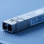
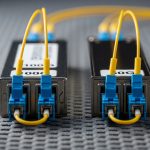
Before you compare prices, validate the electrical and optical envelope. For an OSFP 800G transceiver, the most consequential specs are wavelength band (or multimode grading), nominal reach, lane configuration, optical power consumption, and the connector type (LC for fiber, with simplex or duplex cabling depending on the optics design). You also need operating temperature range because AI deployments often run in constrained airflow zones.
Below is a comparison template you can map to the exact part numbers you are considering. Always confirm against the switch vendor compatibility list and the optics vendor datasheet for the specific OSFP SKU.
| Spec | Typical OSFP 800G SR Variant | Typical OSFP 800G Long-Reach Variant | What to check in your BOM |
|---|---|---|---|
| Data rate | 800G | 800G | Ensure the switch supports 800G on that port mode |
| Optical medium | Multimode fiber (OM4/OM5) | Single-mode fiber (SMF) | Match to your existing fiber plant |
| Nominal reach | Short-reach (tens of meters class) | Long-reach (hundreds of meters class) | Confirm with link budget, not just marketing reach |
| Connector | LC duplex (common) | LC duplex (common) | Verify duplex polarity and patch panel layout |
| TX optical power | Vendor-specific | Vendor-specific | Check min/max launch power and receiver sensitivity |
| Receiver sensitivity | Vendor-specific | Vendor-specific | Assess margin versus patch loss and bends |
| Power consumption | ~single-digit watts class (varies) | ~single-digit watts class (varies) | Model PSU and thermals at rack level |
| Operating temperature | Typically industrial or extended range | Typically industrial or extended range | AI halls can exceed comfort zones during peak load |
In the field, interoperability issues often surface as “link comes up then flaps” or “transceiver not recognized” during boot. Those symptoms are frequently tied to DOM support, threshold settings, or a platform’s strict implementation of transceiver type recognition. Vendor datasheets and switch release notes are your best sources for compatibility constraints. For optics examples you may encounter in procurement, look at vendor families such as Cisco and third-party compatible OSFP 800G SR and LR modules, including SKUs like Cisco SFP-10G-SR analogs at smaller speeds, and OSFP offerings from vendors such as Finisar and FS.com (always confirm OSFP 800G, not QSFP28 or QSFP56 by mistake). For a starting point on vendor documentation, see [Source: Cisco] [[EXT:https://www.cisco.com/c/en/us/support/index.html]] and [Source: Finisar] [[EXT:https://www.lumentum.com/]].
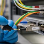
Pro Tip: In AI pods, your biggest hidden variable is not the reach spec; it is patch panel and connector loss drift after repeated maintenance. Measure end-to-end insertion loss and verify polarity before you blame the OSFP 800G transceiver itself.
Real-world deployment scenario: AI pod leaf-spine with tight airflow
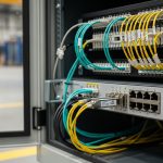
Consider a hyperscale AI pod with a leaf-spine topology: 48-port 800G-capable leaf switches connect to 12 spine switches. Each leaf has 32 active 800G east-west links plus spare for growth, and the pod spans four rows of racks. The fiber plan uses OM5 multimode for adjacent rack distances up to about 50 meters, with patch panels in each row; the remainder uses single-mode for longer jumps between row clusters.
Engineers deploy OSFP 800G optics in two phases. First, they validate in a pilot row by running 24-hour soak tests at line rate with packet counters and optical telemetry polling from the switch. Second, they roll into production after confirming that DOM readings (temperature, bias current, and optical power) remain within vendor thresholds across peak inlet temperatures. During one rollout, a subset of links showed intermittent CRC errors when patch panels were reworked; root cause was connector cleanliness and a polarity mismatch, not an optics mismatch. The fix was re-terminating affected LC connectors and updating the patch labeling process.

How to choose the right OSFP 800G transceiver: decision checklist
When you evaluate OSFP 800G transceivers, treat it like a system component with constraints across architecture, operations, and governance. Use this ordered checklist to avoid expensive re-cabling or avoidable downtime.
- Distance and fiber type: pick OM4/OM5 or SMF based on measured insertion loss and bend constraints.
- Switch compatibility: confirm the exact OSFP 800G SKU is supported on your switch model and software release.
- Reach and link budget margin: validate against patch loss, coupler loss, and aging; do not rely only on nominal reach.
- DOM and telemetry behavior: ensure your monitoring stack can parse vendor DOM; check alarm thresholds and reset behavior.
- Operating temperature and airflow: verify the transceiver’s temperature range matches your inlet and exhaust conditions.
- Power and PSU headroom: model total transceiver draw per rack and validate PSU efficiency at peak load.
- Vendor lock-in risk: compare OEM-only versus third-party options, factoring interoperability support and RMA terms.
Common mistakes and troubleshooting tips in the field
Even experienced teams can stumble when scaling OSFP 800G transceiver rollouts. Here are frequent failure modes, root causes, and fixes that show up in operations.
- Mistake: Using the correct form factor but the wrong fiber type (OM4/OM5 vs SMF) or wrong reach class.
Root cause: procurement substituted a “similar-looking” OSFP SKU or a lab-tested module was assumed to be generic.
Solution: lock part numbers in change control, require proof of optical budget for the installed fiber, and verify connectorization at the patch panel. - Mistake: Link comes up intermittently with CRC or FEC-related counters increasing.
Root cause: dirty LC connectors, damaged ferrules, or marginal insertion loss after maintenance.
Solution: clean connectors with approved methods, inspect with a fiber scope, and re-test OTDR or insertion loss across the full path. - Mistake: Transceiver not recognized or fails during reboot.
Root cause: DOM compatibility mismatch, unsupported vendor identifier behavior, or platform software needing an optics profile update.
Solution: confirm switch software release notes for transceiver support, validate DOM parsing in your NMS, and escalate with vendor logs (DOM alarms, module ID, and link events). - Mistake: Exceeding thermal limits during high utilization.
Root cause: airflow bypass, blocked vents, or uneven rack fan performance leading to elevated module temperature.
Solution: run telemetry-based thermal checks, adjust fan profiles, and re-seat airflow baffles to restore predictable cooling.
Cost and ROI note: OEM vs third-party optics under real TCO
Pricing for an OSFP 800G transceiver typically varies by reach class and vendor support model. In practice, OEM optics often carry a premium for validated compatibility and faster RMA processing; third-party modules can reduce unit cost but may shift operational burden into integration testing and incident handling. As a planning baseline, many buyers see wide ranges depending on market timing and contractual volume, so treat quotes as time-sensitive and normalize by total installed risk.
ROI should include: expected failure rate over the first year, RMA turnaround time, labor cost for swap and validation, and power and cooling impacts. If third-party optics require additional troubleshooting time during incidents, the savings can evaporate quickly. Conversely, when compatibility is proven and DOM telemetry is stable, third-party optics can yield meaningful TCO reductions by lowering procurement cost and increasing spares flexibility.

FAQ
What distances are OSFP 800G transceivers typically used for?
It depends on whether you select multimode (OM4/OM5) or single-mode variants. Use measured insertion loss and bend constraints to confirm margin rather than assuming nominal reach is sufficient. Your switch vendor compatibility guide will also indicate supported fiber types and optics families.
Can I mix OEM and third-party OSFP 800G transceivers in the same switch?
Sometimes yes, but it is not guaranteed. Compatibility depends on the switch software release, DOM behavior, and the module identification method. Plan a controlled pilot and validate telemetry alarms and link stability before broad mixed-vendor deployment.
How do I verify DOM support for monitoring and governance?
Confirm that your NMS or monitoring platform can read key DOM fields and that alarm thresholds align with your operational policies. Validate during a soak test and capture module reset events, temperature excursions, and optical power telemetry under load.
What is the most common cause of OSFP 800G link instability?
In many real deployments, it is connector cleanliness or patch panel loss/polarity issues rather than the transceiver itself. Clean and scope connectors, verify polarity, and re-check end-to-end insertion loss when CRC or error counters rise.
Do OSFP 800G optics affect rack power and thermal planning?
Yes. Even if each module uses only a few watts, high port density can noticeably increase rack-level power draw and heat load. Model transceiver power plus switch base consumption and validate inlet temperature margins during peak utilization.
What documents should I require during procurement?
Require switch vendor compatibility documentation, the optics vendor datasheet for the exact OSFP SKU, and any test reports related to DOM and interoperability. For governance,