In leaf-spine data centers, the fastest path to higher throughput often runs into a practical bottleneck: optics compatibility, power budgets, and fiber plant limits. This article helps network engineers and data center architects choose between 400G and 800G migration optics with an optics comparison focused on SR8 and DR8 classes, DOM behavior, and real operational constraints. You will get concrete selection checklists, troubleshooting patterns, and a cost-aware ROI view for planning change windows.
Why 400G to 800G migrations stress your optics choices
Moving from 400G to 800G is not just a port-speed upgrade; it changes how you map lanes, how you manage reach, and how much thermal and power headroom you need in optics and switch line cards. In practice, field teams see failures when optics are “electrically compatible” but not “system compatible” due to vendor-specific requirements for FEC mode, lane mapping, or digital diagnostics (DOM) polling. If your fiber plant was built for 12-fiber or 8-fiber conventions, you may also face a reach-versus-connectivity tradeoff that shows up during cutover.
At the standard level, the industry is anchored by IEEE 802.3 Ethernet optical link definitions and by vendor datasheets for specific transceiver families and switch optics support matrices. For example, 400G and 800G Ethernet over optical interfaces are aligned with IEEE 802.3 lane and coding behavior; however, the operational details (such as DOM thresholds and supported FEC) are enforced by switch firmware and optics qualification. [Source: IEEE 802.3]

400G vs 800G optics comparison: SR8 and DR8 in real deployments
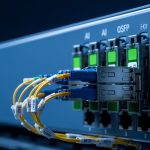
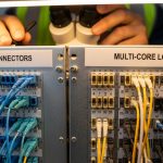
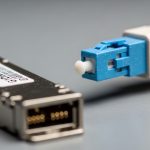
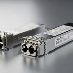
The most common 400G-to-800G step in enterprise and hyperscale environments is using parallel optics families that match the switch’s expected connector and transceiver form factor. Typically, 400G SR8 uses an 8-lane parallel approach over multimode fiber, while 800G SR8 expands the parallelization and lane count to deliver double the aggregate throughput. For longer reach, 400G and 800G DR8 variants target single-mode fiber with higher loss budgets and different optics power/receiver sensitivity requirements.
Key specs to compare before you touch the patch panel
Before ordering parts, compare wavelength, nominal reach, connector type, and the expected operating temperature of the transceiver. Also check whether your switch requires a specific FEC or coding mode for the link to come up cleanly. The table below summarizes the typical engineering targets you will see across SR8 and DR8 classes for 400G and 800G Ethernet.
| Category | 400G SR8 (Typical) | 800G SR8 (Typical) | 400G DR8 (Typical) | 800G DR8 (Typical) |
|---|---|---|---|---|
| Data rate | 400 Gbps | 800 Gbps | 400 Gbps | 800 Gbps |
| Wavelength | 850 nm class (MM) | 850 nm class (MM) | ~1310 nm class (SM) | ~1310 nm class (SM) |
| Reach target | ~100 m on OM4 class (varies) | ~100 m on OM4 class (varies) | ~500 m on SM (varies) | ~500 m on SM (varies) |
| Fiber type | Multimode (e.g., OM4) | Multimode (e.g., OM4) | Single-mode (e.g., OS2) | Single-mode (e.g., OS2) |
| Connector | MT/MPO-12 or MPO-16 class (platform dependent) | Higher-count MPO (platform dependent) | LC or MPO (platform dependent) | LC or MPO (platform dependent) |
| DOM support | Vendor-specific; typically I2C with thresholds | Vendor-specific; typically I2C with thresholds | Vendor-specific; typically I2C with thresholds | Vendor-specific; typically I2C with thresholds |
| Operating temp | Commonly 0 to 70 C (check datasheet) | Commonly 0 to 70 C (check datasheet) | Commonly 0 to 70 C (check datasheet) | Commonly 0 to 70 C (check datasheet) |
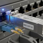
Because exact specs vary by switch vendor and module generation, verify the optics compatibility matrix for your specific switch model and transceiver part number. As concrete examples of part families you may encounter, 10G SR and 25G/40G optics are widely documented, but for 400G/800G you should rely on the exact 400G/800G transceiver datasheets from vendors such as Cisco and Finisar/FS, and the switch vendor’s validated list. [Source: Cisco QSFP-DD transceiver datasheet][Source: Finisar transceiver documentation]
Pro Tip: In many migrations, the first link failures are not “bad optics,” but DOM threshold mismatches and FEC negotiation differences after firmware upgrades. Capture link bring-up logs for both the old 400G optics and the new 800G optics in the same chassis so you can compare error counters and DOM alarm events during the same maintenance window.
Migration patterns that reduce risk: keep reach, change lanes
When planning the 400G to 800G migration, you want to minimize variables. A reliable pattern is to standardize on a single fiber class (MM for short, SM for longer) and keep reach within the validated budget for the module family and your fiber loss. If you already have OM4 and MPO trunks engineered for parallel optics, the SR8 path often yields the fastest cutover with fewer change requests.
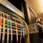
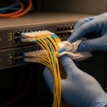
For DR8, the operational advantage is distance headroom over longer top-of-rack to aggregation spans, but it can introduce more variables: polarity, fiber type consistency, and connector cleanliness. In a field environment, you will often see intermittent CRC errors caused by marginal end-face cleanliness rather than a pure optical power issue. That is why dust inspection and standardized cleaning procedures matter as much as selecting the right reach class.

Selection criteria checklist for optics comparison (400G vs 800G)
Engineers typically shortlist optics based on what the switch will actually accept and what the fiber plant can support. Use this ordered checklist during procurement and pre-install validation:
- Distance vs validated reach: Measure or estimate total link loss and confirm it is within the module’s budget for your exact fiber type (OM4 vs OM5, OS2 variants) and connector quality. Don’t rely on marketing reach alone.
- Switch compatibility matrix: Confirm the switch model supports the exact transceiver family and DOM/FEC expectations. Even two optics that both say “SR8” can behave differently across platforms. [Source: vendor switch documentation]
- Connector and polarity constraints: Validate MPO/MT connector count and polarity rules (including whether your patching uses MPO polarity A/B). Mistakes here cause “link up but traffic errors” or total link failure.
- DOM behavior and alarm thresholds: Ensure the transceiver reports temperatures, bias currents, and receive power in a way your monitoring stack can interpret. Watch for vendor-specific units and threshold settings.
- Operating temperature and airflow: Verify that the module’s rated range matches your cabinet thermal profile. In high-density rows, optics can run close to upper limits during peak load.
- Vendor lock-in risk: Decide whether to standardize on OEM optics or allow third-party modules. Third-party can reduce unit cost, but you must validate DOM, firmware behavior, and supportability.
- Spare strategy and failure handling: Plan for redundancy. In many sites, the cost of downtime outweighs a small module price delta.
Common pitfalls and troubleshooting tips during optics comparison
Even well-planned upgrades can fail. Below are concrete issues that show up in the field for 400G to 800G optics migrations, with root causes and fixes.
Link does not come up after swapping to new 800G optics
Root cause: The transceiver is not on the switch’s validated list, or the switch firmware expects a specific FEC/coding mode for that port. Sometimes the module is electrically compatible but not operationally supported.
Solution: Confirm switch software version and optics support matrix; test with a known-good OEM module for that platform in the same port group before escalating. Log port diagnostics immediately on failure.
Link comes up, but you see rising CRC or FEC error counters
Root cause: Marginal fiber end-face cleanliness, damaged MPO/LC connectors, or incorrect MPO polarity mapping. For parallel optics, a single bad lane can degrade overall link quality.
Solution: Clean and inspect connectors with a microscope, re-terminate or replace any suspect jumpers, and verify MPO polarity against the patching standard used in your data hall.
Intermittent dropouts under thermal load
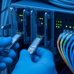
Root cause: Insufficient airflow or blocked vents causing optics temperature to drift upward. Many QSFP-DD style optics have tight operating envelopes, and bias currents can become unstable near the upper end.
Solution: Measure inlet and module temperatures (where supported), ensure fan tray profiles match the planned load, and confirm airflow baffles are in place. If needed, schedule an airflow remediation before further optics swaps.
DOM alarms flood monitoring after the cutover
Root cause: Monitoring thresholds are tuned for the previous optics generation. DOM field names and units may differ slightly across vendors.
Solution: Compare DOM readings from old and new optics during a controlled window, update monitoring thresholds, and validate alert routing. Keep an audit trail so support teams can correlate incidents to specific optics batches.
Cost and ROI note: what you should budget for 400G to 800G
In most procurement cycles, the unit price difference between 400G and 800G optics is meaningful, but the bigger ROI driver is downtime risk and rework cost. As a practical planning range, many teams see OEM-grade 800G optics priced at roughly 2x to 4x the cost of comparable 400G optics depending on reach class and vendor. Third-party modules can reduce line-item cost by 10% to 30%, but you must factor validation time, potential support friction, and the risk of “works in lab, fails in production” DOM/FEC edge cases.
TCO also includes operational overhead: cleaning supplies, spares inventory, and the time technicians spend verifying polarity and diagnostics. If your cutover window is tight, a slightly higher optics unit price for validated OEM modules is often cheaper than a multi-day rollback caused by unexpected behavior.

FAQ: optics comparison for 400G to 800G migration
Do I need to change the fiber plant when going from 400G to 800G?
Not always. If you already have the correct fiber type (OM4/OM5 for SR8, OS2 for DR8) and MPO trunking/polarity standards are consistent, you can often keep the plant. The key is validating total link loss and connector quality against the exact 800G optics family and your switch’s validated reach.
Is SR8 always the best choice for data center top-of-rack links?
SR8 is often best for short distances due to lower complexity and simpler fiber handling. However, if your spans exceed validated reach or you have mixed cabling, DR8 may reduce rework by matching the actual topology distances.
Will third-party optics work the same as OEM optics?
They can, but you must validate on your specific switch model and firmware version. Watch for DOM field differences, FEC negotiation behavior, and supportability constraints during escalation. If you cannot run a meaningful validation, treat OEM optics as the safer default for production.
How do I verify MPO polarity before installing 800G SR8 optics?
Use your site’s documented polarity standard and confirm the patching direction with a consistent labeling scheme. Then test with a known-good transceiver and check port counters immediately after link bring-up to catch lane issues early.
What are the first logs to capture when an 800G link fails?
Capture port link status, transceiver DOM alarm states, and optical/electrical error counters (CRC/FEC or equivalent) at the moment of failure. Compare against a working port in the same chassis to separate optics faults from broader firmware or port configuration issues.
When should I plan a rollback?
Rollback when you cannot isolate the issue to a specific connector cleanliness problem, optics compatibility gap, or firmware mismatch within your maintenance window. If error counters spike across multiple ports simultaneously, suspect switch configuration or firmware compatibility before swapping large numbers of optics.
For a successful 400G to 800G migration, the optics comparison you care about is the one tied to your switch validation, DOM behavior, and your real fiber loss and polarity constraints. Next, review your topology’s reach assumptions and connector standards using optics reach planning for data centers.
Author bio: I lead network reliability and optical transport planning for high-density data centers, with hands-on experience validating transceivers against switch firmware and DOM telemetry. I focus on reducing cutover risk through measurable link budgets, disciplined fiber hygiene, and pragmatic build-vs-buy choices.