When a leaf-spine link flaps or stays dark, engineers often waste time swapping optics without proving the root cause. This article is a hands-on optical troubleshooting playbook for data center networks, built for NOC engineers and field techs who need repeatable checks. You will learn how to validate fiber polarity, optical power, transceiver health, and switch compatibility using practical measurements and vendor-realistic workflows.
Prerequisites: set up your optical troubleshooting lab safely
Before touching hardware, standardize your workflow so results are comparable across racks and vendors. In practice, I keep a small “optics kit” with a calibrated optical power meter, a known-good patch cord set, and a label system for fiber IDs. The goal is to reduce blind swaps and make every observation traceable to a specific port and fiber pair. If you are doing this during an outage window, pre-stage the tools so each step takes minutes, not hours.
Tools and reference items you should have
- Optical power meter + adapter set for LC/SC, plus an attenuator if you need to simulate loss budgets.
- Light source or visual fault locator (VFL) for basic fiber presence checks.
- Known-good transceivers (at least one SR and one LR style) matching your switch vendor’s supported list.
- Cleaning supplies: lint-free wipes and proper fiber cleaning cassette.
- Labeling: port-to-fiber mapping sheet for each ToR or spine switch.
Environmental and safety checks
Verify you are working within safe handling limits for fiber and optics. Many SFP/SFP+/QSFP modules are sensitive to connector contamination, and repeated insertion without cleaning is a fast path to elevated error rates. Also confirm your transceiver temperature is within the vendor’s operating range; a marginal airflow condition can look like “bad optics.” For reference, typical pluggables list an operating temperature around 0 to 70 C (varies by manufacturer and form factor).

Step-by-step workflow: diagnose optical link symptoms with measurements
Start from symptoms and narrow the search in the order that minimizes disruption. A disciplined sequence is: confirm link state, confirm optics compatibility, measure receive/transmit power, validate fiber polarity and cabling, then inspect DOM and physical cleanliness. This sequence helps because the most common root causes are cabling/polarity errors and dirty connectors, which can be detected early without replacing parts.
Capture the exact failure signature from the switch
Record whether the interface is down, flapping, or up but with high CRC/FEC errors. On many platforms, you can pull interface counters and optical DOM data. Capture timestamps so you can correlate with environmental events like fan speed changes or patch panel moves.
Expected outcome: You know whether the failure is “no light,” “weak light,” or “light present but errors.”
Confirm optics type, speed, and vendor compatibility
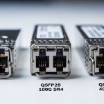
Do not assume “SR is SR.” Verify the module type and speed match the port profile: for example, 10G SR modules should not be used in a 1G-only SFP slot, and 40G QSFP+ optics differ from 100G QSFP28 optics. Check switch transceiver qualification lists when available, and treat vendor mismatch as a variable, not a conclusion.
Expected outcome: You eliminate configuration mismatches that cause link negotiation failures.
Measure optical power and compare to the module budget
Using your power meter, measure Tx optical power (from the transmitter side) and Rx optical power (at the receiver side) if your setup supports it. Compare against the transceiver datasheet’s typical launch power and receiver sensitivity for the exact wavelength and data rate. If you cannot measure Tx directly, measure Rx and infer whether the link is within budget based on your known fiber attenuation and patch cord lengths.
Expected outcome: You can classify the fault as “power too low,” “power too high,” or “power present but errors.”
Validate fiber polarity and mapping end-to-end
For duplex LC cabling, polarity errors are a top cause of “link up/down loops” and high BER. Confirm that the transmit fibers connect to the receive fibers across the entire path, including any MPO/MTP trunk assemblies and patch cords. If you use MPO-to-LC fanouts, ensure the polarity method matches your cabling standard (for example, polarity A/B variations used in 40G/100G deployments).
Expected outcome: The optical path is correct for both transmit and receive directions.
Inspect and clean connectors before any replacement
Even a small amount of contamination can raise loss enough to cause intermittent errors. Clean both sides of the link: transceiver receptacle and patch cord plug. After cleaning, re-seat the modules and re-check DOM alarms and interface counters.
Expected outcome: You reduce connector-related attenuation and stabilize link performance.
Read DOM and correlate with temperature and bias current
DOM values help you detect aging optics, bias current drift, and thermal stress. Look for abnormal transmit power, elevated receive power (can indicate reflection or mis-cabling), and temperature outliers. If the switch exposes DOM fields, log them for before/after comparison.
Expected outcome: You identify whether the optic itself is degrading or whether the problem is external (fiber, connector, or configuration).

Key optical parameters that decide success: SR vs LR and power budgets
Optical troubleshooting becomes faster when you internalize the parameters that actually move the needle: wavelength, reach, launch power, receiver sensitivity, and connector type. For data centers, most failures cluster around short-reach multimode optics (SR) and patching infrastructure. Still, you should be able to reason about single-mode links too, because a swapped SM module can cause immediate link failure or persistent errors.
Quick comparison table for common pluggables
The values below are representative ranges from widely deployed datasheets; always confirm the exact model number you installed and its datasheet before concluding a measurement is out of spec.
| Module family | Typical wavelength | Target reach | Connector | DOM support | Operating temp range | Example part numbers |
|---|---|---|---|---|---|---|
| 10G SR (multimode) | 850 nm | ~300 m (OM3/OM4 dependent) | LC duplex | Yes (common) | ~0 to 70 C | Cisco SFP-10G-SR, Finisar FTLX8571D3BCL, FS.com SFP-10GSR-85 |
| 40G SR4 (multimode) | 850 nm | ~100 m (OM3/OM4 dependent) | MPO/MTP | Yes (common) | Common QSFP+ SR4 models from Cisco/Arista-compatible vendors | |
| 100G SR4 (multimode) | 850 nm | ~100 m (OM4 often) | MPO/MTP | Yes (common) | Common QSFP28 SR4 models from major OEMs | |
| 10G LR (single-mode) | 1310 nm | ~10 km | LC duplex | Yes (common) | 0 to 70 C typical | Vendor-specific 10GBASE-LR SFP+ modules |
Standards and why they matter during troubleshooting
IEEE 802.3 defines Ethernet PHY behaviors, but the practical operational limits come from transceiver and cabling specs. For short reach, multimode requirements depend heavily on OM type (OM3 vs OM4), patch cord quality, and insertion loss. For single-mode, fiber quality and connector cleanliness dominate, especially around splices and dirty LC endfaces.
References: [[EXT:https://standards.ieee.org/standard/802_3 IEEE 802.3]] and vendor datasheets for the exact transceiver model.
Pro Tip: If DOM shows “Tx power normal but Rx power near zero,” treat it as an optical path problem first (polarity, wrong fiber pair, or dead patch cord) rather than immediately replacing the module. In real data center work, swapping optics without verifying the fiber mapping wastes the most time and often increases connector contamination.

Selection criteria checklist: choose optics and test strategy that prevent repeat outages
Optical troubleshooting is easier when you select modules and test methods that align with your environment. Use this ordered checklist during procurement and during incident response planning. The goal is to reduce “unknown unknowns” like undocumented compatibility quirks or missing DOM data.
- Distance and fiber type: confirm OM3/OM4 or single-mode, and verify patch cord lengths and insertion loss.
- Switch compatibility: use the switch vendor’s supported transceiver list and verify speed settings (10G, 25G, 40G, 100G).
- DOM and visibility: ensure the platform reads DOM fields reliably for your module type; you need Rx power and bias current to troubleshoot quickly.
- Operating temperature and airflow: check module operating range (commonly ~0 to 70 C) and verify airflow direction and fan curves.
- Connector and cleaning practicality: LC duplex vs MPO/MTP fanouts change cleaning and polarity risk; plan cleaning tools accordingly.
- Vendor lock-in risk and interoperability: third-party optics can work, but qualification varies by switch model; keep at least one known-good OEM module for controlled comparisons.
- Power budget margin: do not run at the edge; aim for comfortable link margin so aging optics and cleaning variability do not push you into intermittent errors.
Expected outcome: You reduce recurrence by preventing “it should work” optics choices and by ensuring your future optical troubleshooting has the right telemetry.
Common mistakes and troubleshooting tips: root cause to fix
Even experienced teams fall into repeat failure loops. Below are the most common optical troubleshooting failure modes I see in data centers, with root causes and concrete solutions.
Pitfall 1: Swapping optics before cleaning and polarity verification
Root cause: Dirty connector ferrules or polarity mismatch can produce near-zero Rx power and intermittent link behavior. Swapping optics adds contamination cycles and delays isolation. Solution: Clean both ends, verify polarity and fiber mapping, then measure Rx power before replacing modules.
Pitfall 2: Using the wrong fiber pair or incorrect MPO polarity method
Root cause: Patch panel labels are often wrong after re-cabling, and MPO polarity A/B differences can invert lanes. This can yield consistent “link down” or high error rates without an obvious physical damage indicator. Solution: Trace the fiber end-to-end, confirm transmit-to-receive pairing, and use known-good patch cords or polarity test fixtures when available.
Pitfall 3: Assuming “compatible” means “same power budget” across vendors
Root cause: Third-party optics may meet nominal specs but have different launch power, spectral characteristics, or DOM reporting behavior. That can cause marginal links that pass initial tests but fail under temperature drift. Solution: Compare measured Rx power to the datasheet sensitivity and validate DOM readings; keep an OEM reference optic for A/B testing.
Pitfall 4: Ignoring environmental airflow and thermal throttling effects
Root cause: If a rack experiences reduced airflow, module temperature rises and bias current changes, increasing BER or causing intermittent link drops. Solution: Check switch sensor logs, verify fan speed and filter health, and ensure transceivers are seated correctly with unobstructed airflow.
Expected outcome: You convert chaotic incidents into repeatable isolation steps.
Real-world deployment scenario: leaf-spine 10G SR in a busy data center
In a 3-tier data center leaf-spine topology, a team runs 48-port 10G ToR switches with 12 uplinks to spines using 10GBASE-SR over OM4. During a patch window, one ToR uplink starts flapping every 30 to 60 seconds, while other uplinks remain stable. The first observation shows interface down/up events plus rising CRC counters when the link returns. Using optical troubleshooting, the team checks DOM and finds Tx power near normal but Rx power oscillating near the sensitivity threshold; after cleaning the LC connectors at the patch panel and correcting a mis-labeled fiber pair, the link stabilizes and CRC counters drop to baseline within minutes.
What made the fix fast
They avoided blind module swaps by measuring Rx power and correlating it with DOM alarms, then verified polarity mapping using the patch panel labels as a starting hypothesis, not as truth. They also used a known-good SR transceiver to confirm the switch port profile was correct. This reduced downtime and prevented additional connector wear from repeated insertions.
Expected outcome: Stable link, reduced incident duration, and improved documentation for future changes.
Cost and ROI note: realistic optics spend and total cost of ownership
In many enterprises, OEM optics for 10G SR often land in the mid-range of $60 to $150 per module, while third-party options may be lower, sometimes $25 to $80. The true TCO is driven by failure rates, troubleshooting time, and downtime risk rather than the sticker price. A single avoided outage can outperform months of savings by preventing repeated truck rolls and minimizing connector damage from unnecessary swaps. If you rely on third-party optics, budget for qualification testing and keep a small “known-good” reference set to accelerate optical troubleshooting.
Expected outcome: You make purchasing decisions that align with operational resilience, not just initial cost.
FAQ: optical troubleshooting questions engineers ask first
How can I tell if it is a dirty connector versus a bad transceiver?
Measure Rx power and check DOM values. If Rx power is near zero and cleaning improves it immediately, contamination is the likely root cause. If Rx power stays abnormal after cleaning and polarity verification, test with a known-good transceiver to isolate the optic.
What DOM alarms matter most during optical troubleshooting?
Focus on transmit power, receive power, bias current, and module temperature. Sudden changes during flaps often indicate an external optical path issue, while steadily drifting bias or temperature can indicate aging or thermal stress.
Can I use third-party optics in a standards-based Ethernet network?
Often yes, but compatibility depends on switch vendor qualification and transceiver behavior. Validate using your switch’s supported list where available and perform a controlled A/B test with one known-good OEM module to confirm power budget and DOM visibility.
Why do MPO links fail even when the fiber looks intact?
MPO failures commonly come from lane polarity mismatches or incorrect fanout alignment rather than physical damage. Confirm the polarity method end-to-end and verify the exact mapping between trunk and breakout using documented patch records.
What is the fastest first action during a sudden “link down” incident?
Check interface state and counters, then verify optics type and port configuration. Next, clean connectors and measure Rx power; if Rx is near zero, treat it as an optical path problem and validate polarity and fiber pair mapping before replacing modules.
How do I prevent repeat optical troubleshooting incidents after moves and changes?
Update fiber mapping documentation at the time of change and include polarity notes for MPO/MTP fanouts. Add a short post-change verification step: DOM sanity check plus Rx power measurement against expected values.
With a measurement-first workflow and disciplined connector and polarity checks, optical troubleshooting becomes predictable instead of stressful. Next, strengthen your resilience by pairing this playbook with maintenance and cabling change management for optical links to reduce repeat failures after every move, add, and change.
Author bio: I design and operate high-availability data center networks, running hands-on optical troubleshooting during production incidents and post-change validation. I focus on telemetry-driven diagnosis, power budget discipline, and operational guardrails that keep links stable under real-world constraints.