In factories, ports, campuses, and edge micro data centers, IoT applications fail in silent ways: dropped packets, link flaps, and rising latency when fiber optics are mis-matched to transceivers. This article helps network and field engineers choose optical modules that fit IEEE Ethernet requirements and real deployment constraints, from temperature swings to connector geometry. You will get selection criteria, a practical comparison table, and troubleshooting patterns you can apply during commissioning.
Where optical transceivers meet IoT applications in the real world
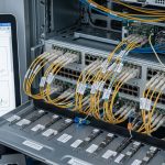
IoT applications often move sensor telemetry from harsh environments to gateways, then onward to aggregation switches and cloud endpoints. The bottleneck is not only bandwidth; it is signal integrity across distance, electromagnetic immunity, and deterministic behavior under load. Fiber links using SFP, SFP28, SFP+ (and QSFP/QSFP28 where applicable) reduce interference compared with copper, improving stability for industrial Ethernet, machine vision, and time-series analytics.
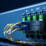
In a typical edge deployment, you might run 10G Ethernet from a ruggedized access switch to an aggregation closet using SR (multimode) for short reach, while LR or ER (single-mode) covers longer spans. The optical transceiver must align with the switch’s host interface expectations, including electrical lane mapping and DOM telemetry support. For standards grounding, Ethernet PHY and link behavior follow IEEE 802.3 (including 10GBASE-SR and 10GBASE-LR families) and vendor datasheets specify exact optical parameters. IEEE 802.3 standard library

Optical module specs that actually determine link success
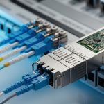
Transceivers are not interchangeable just because they share a form factor. The decisive parameters are wavelength (nm), reach (km or meters), fiber type (MMF vs SMF), connector style (LC vs MPO), optical power levels, receiver sensitivity, and compliance with the relevant IEEE 802.3 clause. On top of the optical layer, the host must provide the correct electrical interface for the module (for example, SFP+ for 10G and SFP28 for 25G).
Most modern modules support Digital Optical Monitoring (DOM) over I2C, exposing laser bias current, optical transmit power, and receiver power. Field engineers use DOM to confirm margin and predict failure before a link goes dark. Vendor datasheets also show temperature ranges; an industrial gateway may sit between -20 C and 70 C, while some enterprise modules are limited to narrower operating conditions.
| Module example | Data rate | Wavelength | Reach | Fiber type | Connector | Optical class (typical) | Operating temp | DOM |
|---|---|---|---|---|---|---|---|---|
| Cisco SFP-10G-SR | 10G | 850 nm | ~300 m (OM3) / ~400 m (OM4) | Multimode | LC | Class 1 laser product | ~0 C to 70 C (model-specific) | Yes |
| Finisar FTLX8571D3BCL | 10G | 850 nm | ~300 m (OM3) / ~400 m (OM4) | Multimode | LC | Class 1 laser product | ~0 C to 70 C (model-specific) | Yes |
| FS.com SFP-10GSR-85 | 10G | 850 nm | ~300 m (OM3) / ~400 m (OM4) | Multimode | LC | Class 1 laser product | ~-5 C to 70 C (model-specific) | Varies by spec |
| Generic note | 25G SR (SFP28) | ~850 nm | Up to ~100 m (OM3) / ~150 m (OM4) | Multimode | LC | Class 1 laser product | Varies | Often yes |
Note: Exact reach and temperature limits vary by part number and vendor datasheets. Always verify against the module’s ordering guide and the switch vendor compatibility list before procurement. [Source: vendor datasheets for Cisco SFP-10G-SR, Finisar FTLX8571D3BCL, and FS.com SFP-10GSR-85]
Pro Tip: During commissioning of IoT applications in the field, do not only verify “link up.” Pull DOM values and confirm optical power margin at the receiver. If you see a receiver power drifting toward the minimum threshold after a few weeks, the root cause is often dirty LC endfaces or a marginal patch cord, not the switch.
Choosing the right transceiver for IoT applications: a decision checklist
When engineers choose optical transceivers for IoT applications, they are balancing physics, compatibility, and operational risk. The best module is the one that maintains link margin across temperature and aging while matching the host interface and software ecosystem.
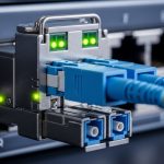
- Distance and fiber type: Determine whether you need multimode (SR) or single-mode (LR/ER). For multimode, confirm OM3 vs OM4 and patch cord lengths.
- Switch compatibility: Check the host switch’s optics compatibility list. Some platforms enforce vendor-specific EEPROM IDs, causing “module not supported” events.
- Data rate and lane mapping: Match the module to the port speed (10G vs 25G vs 40G). A mismatch can force down-negotiation or fail link.
- DOM and telemetry needs: If you want link health for IoT applications, ensure DOM is available and supported by your monitoring stack.
- Operating temperature and enclosure design: Validate module temperature range for outdoor cabinets, cable trays, and sun-heated enclosures.
- Power budget and optical margin: Use the vendor link budget and account for connector loss, splice loss, and patch cord attenuation.
- Vendor lock-in risk: Evaluate OEM vs third-party modules, considering warranty terms and firmware compatibility policies.
Quick rule-of-thumb mapping for edge IoT
If the IoT application traffic stays within a building (tens to hundreds of meters), SR at 850 nm over OM3/OM4 often works with minimal cost and simple LC cabling. If you span across buildings, campus rings, or outdoor routes, single-mode LR/ER modules are usually safer for signal stability. When you upgrade to higher sensor throughput (for example, aggregated machine vision), moving from 10G to 25G may require SFP28 SR modules and a reevaluation of multimode reach.

Common pitfalls and troubleshooting patterns in the field
Even well-chosen optics can fail if the installation details are ignored. The good news is that most issues produce recognizable symptoms, and you can resolve them quickly with a disciplined checklist.
Pitfall 1: Link flaps after thermal cycling
Root cause: The module is operating outside its rated temperature range, or the cage airflow is inadequate. Aging laser bias current and condensation can also contribute in outdoor or poorly sealed cabinets.
Solution: Verify temperature at the switch intake and module region during worst-case conditions. Move to an industrial-grade module with a wider temperature spec, and improve airflow or add a sealed enclosure with controlled ventilation.
Pitfall 2: “Link up” but IoT telemetry shows packet loss
Root cause: Dirty fiber endfaces or damaged patch cords create intermittent attenuation. Another frequent cause is exceeding the link budget by underestimating connector and splice losses.
Solution: Clean LC connectors using approved cleaning tools and inspect with a fiber scope. Re-measure optical power via DOM and compare against vendor thresholds; replace patch cords if needed.
Pitfall 3: Module not supported or falls back to a lower speed
Root cause: EEPROM ID mismatches, unsupported optics profiles, or incorrect port speed configuration. Some switches require specific transceiver compatibility or firmware support for certain third-party modules.
Solution: Check the switch model’s optics compatibility matrix and update switch firmware if the vendor recommends it. Confirm the port is configured for the intended speed and that the transceiver matches the form factor and lane expectations.
Pitfall 4: Multimode used where single-mode was required
Root cause: A campus or outdoor route was treated like an indoor run, but the real distance, dispersion, or attenuation exceeded SR multimode limits.
Solution: Rebuild the link budget and switch to single-mode LR/ER where appropriate. For new builds, standardize cable plants and document fiber type and route length at handoff.

Cost and ROI: what to budget for IoT applications over years
Optical transceivers are often a small line item compared with installation labor and downtime risk, yet the wrong choice can inflate total cost of ownership through premature failures or repeated truck rolls. Typical street pricing varies by vendor, capacity, and temperature grade. As a practical planning range, 10G SR modules commonly fall in a broad bracket such as tens of dollars to low hundreds per unit depending on OEM versus third-party and warranty terms; single-mode LR modules are often higher.
OEM modules may cost more up front, but they frequently reduce compatibility surprises and simplify RMA processes for mission-critical IoT applications. Third-party modules can be cost-effective when your switch vendor supports them and the modules provide consistent DOM behavior. In TCO models, include patch cord replacements, cleaning tools, spare module stocking, and the labor cost of troubleshooting; a single avoidable outage can outweigh the price gap. [Source: vendor pricing surveys and typical enterprise procurement patterns reported by reputable tech media such as TechTarget and Network World]
FAQ for engineers deploying optical transceivers in IoT applications
What optical transceiver type is most common for IoT applications on site?
For short indoor distances, 10G SR at 850 nm over multimode using LC connectors is a common choice because it is economical and easy to deploy. For longer spans or outdoor routes, engineers typically move to single-mode LR/ER to preserve link margin.
Do I need DOM for IoT applications, or is “link up” enough?
For IoT applications that demand reliable telemetry, DOM is valuable because it provides early warning via optical power and laser bias indicators. “Link up” only confirms connectivity, not performance margin under temperature and aging.
Can I mix OEM and third-party transceivers on the same switch?
Often yes, but compatibility depends on the switch model’s optics enforcement and firmware support. If your platform uses strict optics profiles, a third-party module can be rejected or behave unexpectedly.
How do I validate the fiber plant before choosing transceivers?
Measure end-to-end attenuation and verify fiber type (OM3 vs OM4 vs SMF) and connector quality. Use a fiber tester and inspect connectors with a scope before you assume the optics are wrong.
What temperature range should I plan for in industrial IoT deployments?
Plan based on the environment: outdoor enclosures, cable trays, and near-drive areas can exceed typical office conditions. Choose modules rated for the expected ambient temperature and validate airflow around the switch.
When upgrading from 10G to 25G for IoT applications, what changes most?
The module form factor (SFP28 vs SFP+), reach expectations on multimode, and optical budget requirements often change the most. Recheck OM3/OM4 reach assumptions and confirm the switch supports the higher lane rate on those ports.
If you want IoT applications to stay fast and dependable, treat optical transceivers as a system: match wavelength and reach, validate fiber quality, and monitor DOM like a living health signal. Next, explore network monitoring for IoT applications to operationalize telemetry, alerting, and maintenance workflows.
Author bio: I have deployed fiber-based Ethernet links for edge gateways and factory telemetry, validating optical budgets with DOM and field scopes during commissioning. My work focuses on translating IEEE Ethernet requirements and vendor datasheet constraints into repeatable, measurable rollout practices.