When transceivers and optics go scarce, network downtime risk rises fast—especially in leaf-spine data centers, campus rings, and metro transport. This article targets network engineers and field technicians who must keep links stable while parts availability fluctuates. You will get a top list of practical moves for optical resilience, including measurable validation steps, compatibility checks, and troubleshooting patterns grounded in IEEE and vendor guidance.
Top 8 moves for optical resilience when optics are scarce
Build a “known-good optics map” before the shortage hits
In real operations, the fastest recovery comes from knowing exactly which optic types have already proven stable in your environment. Start by inventorying every active port and mapping transceiver part numbers to: vendor, data rate, fiber type, link budget assumptions, and DOM telemetry behavior. During shortages, you can then substitute only within the validated set, reducing the chance of silent incompatibility or unstable optics. This approach supports optical resilience by limiting unknown variables when procurement lead times stretch.
Operational details field teams use: record vendor model numbers and serial-number ranges, and log DOM fields like received power (Rx power), transmit bias, and temperature at steady-state. Keep these values per link so you can spot drift after swapping. Link partners matter too; some switches are pickier about optics thresholds even when standards match.
- Pros: faster swaps, lower outage time, better RCA quality
- Cons: requires disciplined documentation

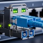
Use standards-based optics, but validate switch compatibility
IEEE 802.3 defines electrical and optical requirements for Ethernet link operation, but vendor implementations still vary in diagnostics, thresholds, and FEC expectations. For example, 10GBASE-SR modules are designed for multimode fiber operation, while 10GBASE-LR targets single-mode. Even within “SR,” optics behavior can differ across vendors, especially around DOM alarm thresholds. Treat standards compliance as necessary, not sufficient, for optical resilience.
What to validate in a test window: insert candidate optics into a spare port, confirm link up/down behavior, check DOM alarms, verify error counters (CRC/FCS, link flaps), and confirm consistent speed negotiation. If your platform uses vendor-specific optics policies, you may need to enable “third-party optics” support or update firmware.
- Pros: reduces substitution risk
- Cons: requires a controlled validation step
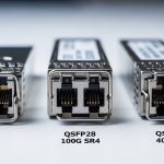
Compare “drop-in alternates” with a real specs table (not vibes)
When supply is constrained, engineers often grab the nearest-looking module. That is how optical resilience fails: wavelength mismatch, wrong fiber type, or unsupported reach assumptions. The table below compares common 10G short-reach and long-reach optics so you can filter candidates quickly before ordering.
| Parameter | 10GBASE-SR (MMF) | 10GBASE-LR (SMF) |
|---|---|---|
| Data rate | 10.3125 Gbps (10G Ethernet) | 10.3125 Gbps (10G Ethernet) |
| Wavelength | ~850 nm | ~1310 nm |
| Typical reach | Up to ~300 m on OM3; varies by link budget | Up to ~10 km on SMF |
| Fiber type | Multimode fiber (OM3/OM4 commonly) | Single-mode fiber (OS2 commonly) |
| Connector | LC (most common for pluggable optics) | LC (most common for pluggable optics) |
| Typical form factor | SFP+ (common) | SFP+ (common) |
| DOM support | Often available; confirm alarms/thresholds | Often available; confirm alarms/thresholds |
| Operating temperature | Commonly 0 to 70 C (check datasheet) | Commonly 0 to 70 C (check datasheet) |
Field note: do not assume that “850 nm SR” means identical launch power, receiver sensitivity, or fiber-mode assumptions. Those differences show up as marginal links with higher error rates under cold/hot swings.
- Pros: speeds up filtering and procurement decisions
- Cons: still needs platform validation

Pre-position spares using a “risk-weighted” stocking model
Optical resilience is not just about having spare optics; it is about placing them where the probability-weighted impact is highest. For each switch, compute a simple risk score: number of dependent services on that ToR/spine uplink, historical link flap frequency, and current lead time for your most-used transceiver. Then stock spares for the highest score first, including one “alternate vendor” option if your platform supports it.
Measurable approach: prioritize optics that serve aggregation uplinks and inter-rack connections. Keep at least one spare per transceiver type per critical chassis, and store them in ESD-safe packaging with humidity control. In shortages, you may reuse spares across sites, but only if you can restore the original DOM baselines afterward.
- Pros: better uptime with limited inventory
- Cons: requires basic analytics and disciplined rotation
Validate optical power budgets with DOM telemetry and error counters
During substitution, you want proof that the link is operating comfortably, not merely “link up.” Use DOM telemetry to compare candidate optics to known-good baselines: Rx power, Tx bias current, and module temperature. Then confirm Ethernet health by checking interface error counters and link flaps over at least 30 to 60 minutes under normal traffic.
Practical thresholds engineers watch: treat a large Rx power delta versus baseline as a red flag for fiber damage, connector contamination, or marginal optical budget. Also watch for increasing CRC/FCS errors, which can indicate a near-threshold receiver or dirty connectors. This is central to optical resilience because it catches “looks fine now” failures.
- Pros: reduces latent failures
- Cons: takes time to measure and trend
Plan for fiber-side resilience: contamination and patching discipline
Supply shortages often tempt teams to blame optics, but many link issues stem from fiber connectors, dust, or patch cord mismatches. During replacements, verify connector cleanliness using inspection tools and clean with manufacturer-approved methods. Confirm polarity, especially for LC duplex patching, and check that the correct fiber strand is mapped to the correct port.
Operational safeguard: when swapping modules, re-check both ends of the patch path and log the cleaning action. In practice, a “successful swap” that still yields higher error rates is frequently a fiber problem masquerading as an optics problem. Optical resilience improves when you treat the physical layer as part of the supply strategy.
- Pros: fixes root causes, not symptoms
- Cons: requires inspection tools and training

Keep firmware and diagnostics aligned with your transceiver strategy
Some platforms enforce optics compatibility via firmware policies, affecting third-party module acceptance and DOM interpretation. Before large-scale substitutions, verify your switch firmware version is compatible with the optics ecosystem you plan to use. If you need to update, do it in a maintenance window and confirm monitoring dashboards correctly interpret DOM fields.
Why it matters: inconsistent DOM alarm thresholds can cause false positives or hide real degradations. Also ensure that your management system is not treating minor DOM differences as critical faults. Optical resilience depends on reliable observability as much as on hardware availability.
- Pros: fewer surprises during swaps
- Cons: change-control overhead
Maintain a fallback topology strategy when optics are delayed
If procurement lead times exceed your outage tolerance, you need a network-level fallback. Examples include rerouting uplinks over alternate spare fibers, using redundant paths in your design, or temporarily operating at a lower-risk segment boundary. Validate that your routing and link aggregation configuration (such as LACP behavior) will not oscillate when links come and go.
Best-fit scenario: in a campus ring with dual-homed access switches, you can temporarily shift traffic to the surviving direction while ordering the correct optics. This keeps optical resilience aligned with application continuity. When the correct modules arrive, you restore the planned topology and re-baseline telemetry.
- Pros: buys time during shortages
- Cons: requires careful traffic engineering
Selection criteria checklist (engineers actually use)
- Distance and fiber type: confirm MMF vs SMF, OM3/OM4 vs OS2, and connector endface cleanliness.
- Reach and link budget: compare required optical power margin, not just nominal reach.
- Switch compatibility: check vendor optics compatibility lists and firmware requirements.
- DOM support and monitoring: verify alarms, thresholds, and whether your NMS interprets DOM correctly.
- Operating temperature: confirm module temperature range matches worst-case rack ambient and airflow.
- Vendor lock-in risk: evaluate third-party acceptance and plan alternate vendors where supported.
- Supply lead time and warranty terms: consider replacement logistics and RMA turnaround.
Common mistakes and troubleshooting tips
Mistake 1: Substituting “same wavelength” optics without checking fiber type
Root cause: 850 nm MMF optics installed on SMF (or vice versa) leads to no link or intermittent link due to severe optical mismatch. Solution: verify fiber type at the patch panel label and trace back to the MPO/LC type and cable construction; then confirm with a known-good loopback or OTDR where available.
Mistake 2: Ignoring DOM telemetry deltas after a successful link-up
Root cause: optics may meet nominal sensitivity but operate near threshold due to connector loss, aging, or different launch power. Solution: compare Rx power and Tx bias to baselines and monitor CRC/FCS and link flap counters for at least an hour under typical load.
Mistake 3: Skipping connector inspection and cleaning during swaps
Root cause: dust on LC endfaces increases insertion loss and causes receiver errors that resemble “bad optics.” Solution: inspect each connector with a fiber scope, clean with approved methods, and re-verify link error counters after cleaning.
Mistake 4: Overlooking firmware optics policies and monitoring mismatches
Root cause: a switch may accept a third-party module but mis-handle DOM alarms, causing monitoring blind spots or nuisance alerts. Solution: confirm firmware version compatibility, run a test substitution on a non-critical port, and validate NMS alarm thresholds.
Real-world deployment scenario: leaf-spine data center during shortages
In a 3-tier data center leaf-spine topology with 48-port 10G ToR switches and 2 uplinks per ToR, an operator faced a 6-week shortage for 10GBASE-SR SFP+ modules. They used an optics map to select only validated alternates, then swapped one uplink per ToR during off-peak hours. After insertion, they compared DOM Rx power to baseline and watched interface CRC/FCS errors for 45 minutes. By combining validated substitutions with connector inspection and a temporary reroute over alternate spare fibers, they kept packet loss at near-zero and avoided a full maintenance outage.
Pro Tip: Many “bad optics” cases are actually connector loss events. If the Rx power is consistently offset yet stable and CRC errors rise only after a swap, inspect and clean both LC