A 40-node AI training cluster can look “healthy” at hour one and then degrade fast when optics, optics power budgets, and thermal margins drift under load. This article helps network and infrastructure engineers choose transceivers for optical networking paths that must stay stable during long training runs. You will see a field-style case study, selection criteria, and troubleshooting that maps directly to real switch and cabling constraints.

Problem and environment: why AI traffic exposes optical networking weak points
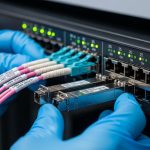
In AI-driven workloads, traffic is bursty, but the failure mode is often physical: marginal link budgets, connector contamination, or transceiver thermal drift. In our case, a research lab deployed a leaf-spine topology supporting model training and data ingestion simultaneously, with 800G and 400G uplinks aggregated across multiple spines. The challenge was not just reaching the target distance; it was ensuring that optics stayed within spec across repeated maintenance cycles, varied fiber cleanliness, and cabinet airflow differences.
Environment specs from the deployment: 3-tier data center layout (ToR leaves, spine core, and an aggregation layer), 48-port ToR switches, and 16 spines. Distances were mixed: 30 m for server-to-ToR patching in one pod, 80 m for ToR-to-spine in another, and 120 m for a remote cabinet row using OM4/OM5 trunks. We also saw a pattern: links that initially negotiated would later flap during sustained GPU runs, suggesting thermal or power/receiver sensitivity stress rather than pure compatibility.
From an standards perspective, link behavior depends on the transceiver’s optical parameters and the host switch’s implementation of common interfaces (for example, IEEE 802.3 for Ethernet PHY behavior, and vendor-specific transceiver management). For optics selection, you also need to respect the transceiver form factor and lane structure (for example, QSFP-DD/OSFP for higher rates) and verify that the switch supports the exact optical module profile you plan to install. References used during validation included vendor transceiver datasheets and switch optics compatibility matrices; for PHY expectations we relied on [Source: IEEE 802.3].
Chosen transceivers: mapping link budget, DOM, and reach to AI paths
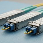
We selected a mix of short- and mid-reach modules to reduce cost while keeping operational stability. For 30 m within pods, we used 10G-SR or 25G-SR-class optics where the switch ports supported them, because the link budget margin is high and the module power is manageable. For 80 m to 120 m ToR-to-spine and cabinet-row links, we moved to longer-reach multimode or active optics depending on fiber type and budget.
In our environment, the deciding factors were: whether the optics matched the switch’s transceiver support list, whether DOM reporting was enabled for monitoring and alerting, and whether the module met the required temperature range for the cabinet airflow profile. DOM matters in AI clusters because you want early warning: rising Tx power or degraded Rx margin can be detected before a run fails.
Specification comparison (what mattered most)
The table below reflects the typical parameters engineers compare when selecting optical networking transceivers for AI-driven workloads. Exact values vary by manufacturer and part number, so always confirm against the specific datasheet.
| Module type | Example part number | Nominal wavelength | Target reach | Connector / fiber | Data rate class | Avg Tx power class | Operating temperature | DOM support |
|---|---|---|---|---|---|---|---|---|
| SR multimode | Cisco SFP-10G-SR (illustrative) | 850 nm | Up to ~300 m on OM3, ~400 m on OM4 (varies) | LC, OM3/OM4 | 10G | Low to moderate (datasheet dependent) | 0 to 70 C typical | Commonly supported |
| SR for higher speeds | Finisar FTLX8571D3BCL (illustrative 25G/50G family) | 850 nm | ~70 m to ~100 m on OM4 (varies by rate) | LC, OM4 | 25G/50G class | Moderate (datasheet dependent) | 0 to 70 C typical | Often supported |
| Longer reach multimode | FS.com SFP-10GSR-85 (illustrative) | 850 nm | ~550 m on OM4 (model dependent) | LC, OM4/OM5 depending on model | 10G | Moderate (datasheet dependent) | 0 to 70 C typical | Varies by SKU |
We also kept an inventory rule: when the switch vendor’s compatibility list allowed it, we prioritized modules from the same ecosystem to reduce unpredictable behavior during firmware upgrades. Where third-party optics were used, we required DOM presence and validated transceiver feature flags before production rollout.
Pro Tip: In many AI deployments, “mystery flaps” are not caused by bandwidth oversubscription. They are often caused by a combination of slightly contaminated connectors and reduced optical power margin that only becomes critical at sustained load. If your platform exposes DOM alarms, watch Tx bias and Rx power trend lines during the first full training cycle, not just link-up events.

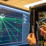
Implementation steps: how we deployed and validated at scale
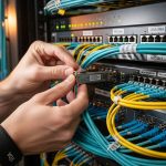
We treated optical networking like a controlled rollout, not a swap-and-hope exercise. First, we matched each link segment’s fiber type (OM3/OM4/OM5), length, and connector cleanliness status to a transceiver SKU with a datasheet-confirmed reach for that fiber category. Second, we verified the switch’s transceiver compatibility and ensured the optics management interface could read DOM values.
Step-by-step checklist we followed
- Measure and document each fiber run length and connector type (LC/SC), then confirm optical loss using a certified test result where available.
- Pick the reach category based on worst-case budget, not nominal datasheet reach. Include patch cord loss, splice loss, and conservative safety margin for aging.
- Confirm switch compatibility for the exact transceiver SKU and form factor (QSFP-DD, QSFP28, SFP+, OSFP, depending on port).
- Enable DOM monitoring and set thresholds for Tx/Rx alarms so you can detect drift during training rather than after failure.
- Validate airflow and temperature in each cabinet. If the transceiver datasheet specifies an operating range, ensure the cabinet stays within it under peak load.
- Run a burn-in test that resembles AI traffic: sustained link utilization plus periodic link renegotiation checks.
During implementation, we found that the most time-saving practice was standardizing labeling and connector cleaning workflow. Every transceiver swap had to use lint-free wipes, inspection microscopes, and consistent dust caps to prevent re-contamination.
Selection criteria and decision checklist for AI-driven optical networking
When engineers choose transceivers for optical networking in AI clusters, the “best” module is the one that stays within spec under operational stress. Below is the ordered checklist we used to decide quickly while minimizing rework.
- Distance and fiber type: verify OM3 vs OM4 vs OM5, and use link budget margins for patch cords and splices.
- Data rate and lane mapping: ensure the module’s supported Ethernet PHY mode matches the switch port configuration.
- Switch compatibility: confirm the exact SKU is supported by the switch hardware and firmware generation.
- DOM and diagnostics: require accessible DOM telemetry for Tx power, Rx power, temperature, and alarm flags.
- Operating temperature: match cabinet airflow; avoid “just within spec” designs in hot aisles.
- Power and thermal load: prefer modules with stable power consumption profiles to reduce local hot spots.
- Vendor lock-in risk: assess TCO tradeoffs between OEM optics and third-party modules with proven compatibility.
Common pitfalls and troubleshooting: what failed in the field
Optical networking failures in AI environments often look like network instability, but the root cause is usually physical or telemetry-related. Here are concrete pitfalls we saw, with causes and fixes.
-
Pitfall 1: Link comes up, then flaps after hours
Root cause: connector contamination or marginal optical power budget that becomes critical as temperature rises during sustained training.
Solution: inspect and clean connectors, then re-check DOM Tx/Rx trend lines under load to confirm margin recovery. -
Pitfall 2: Persistent “unsupported transceiver” alarms
Root cause: module SKU not supported by switch firmware or mismatched form factor/profile.
Solution: validate against the switch vendor compatibility list; if using third-party optics, test in a staging rack before replacing at scale. -
Pitfall 3: Uneven performance across cabinets
Root cause: different airflow patterns cause transceiver temperature drift, reducing receiver sensitivity margin.
Solution: compare cabinet inlet temperatures to the module datasheet operating range; adjust airflow and verify intake filters and baffles. -
Pitfall 4: “Bad optics” blamed when it is actually fiber loss
Root cause: excessive patch cord loss, incorrect fiber grade, or unmeasured splice issues.
Solution: re-test with certified OTDR or loss testing; replace the worst-performing segment rather than swapping the entire optics batch.
Cost and ROI note: where the money really goes
In practice, third-party optics can reduce purchase price, but TCO depends on failure rate, validation effort, and downtime cost. Typical market pricing for short-reach modules may range from tens to low hundreds of dollars per transceiver for lower-speed SKUs, while higher-speed multiport optics for QSFP-DD class can be substantially more. The ROI usually comes from two levers: reducing field failures through compatibility and cleanliness discipline, and lowering energy use by selecting optics with predictable power draw and stable thermal behavior.
In our rollout, the biggest cost avoidance came from DOM-based early detection. By identifying drift before catastrophic link loss, we reduced unplanned maintenance events during training cycles, which mattered more than the initial optics unit price.

FAQ
What should I verify first when buying optics for optical networking?
Start with the switch compatibility list and the exact port type, then verify reach against your fiber type and measured loss. Finally, confirm DOM support so you can monitor Tx/Rx power and alarms during real training loads. This sequence prevents costly “it should work” assumptions.
Is DOM support mandatory for AI workloads?
Not technically mandatory for basic link operation, but it is operationally valuable for reliability. With DOM, you can trend optical power and temperature, which helps you catch drift before it causes link flaps. For long-running jobs, that reduces downtime risk.
How do I choose between multimode and active optics?
Use multimode when distance and fiber grade (OM4/OM5) meet the reach budget with margin. If you must traverse longer distances, use active optics or coherent solutions appropriate to your rate and link budget. The decision should be driven by measured loss and the specific PHY mode supported by the switch.
What is the most common cause of intermittent failures?
Connector contamination and marginal optical power margin are frequent culprits, especially after maintenance. Temperature effects during sustained GPU runs can turn a “barely OK” link into a failing link. Cleaning and DOM trend validation usually narrow it quickly.
Can I mix OEM and third-party transceivers in the same switch?
Often yes, but only when the switch firmware supports the third-party SKU and the transceiver profile matches expectations. Mixing without validation can lead to inconsistent telemetry, unexpected alarm behavior, or firmware upgrade surprises. Stage and test in a lab rack when possible.
Do I need to follow IEEE 802.3 when selecting optics?
IEEE 802.3 defines Ethernet PHY behavior, but optics selection is still driven by the transceiver datasheet and the switch’s implementation. Use IEEE 802.3 as a baseline for expected link characteristics, then confirm the exact optical parameters for your transceiver SKU and fiber run. [Source: IEEE 802.3]
If you want a repeatable process, document each fiber run, lock optics to switch compatibility, and validate with DOM trend monitoring during a realistic AI workload. Next, compare transceiver form factors and port constraints using optical networking transceiver form factors and port compatibility.
Author bio: A field engineer and reporter who has deployed high-density optical networking for GPU clusters, focusing on optics compatibility, DOM telemetry, and failure forensics under real load. I write practical guidance grounded in switch/vendor constraints and operational measurements from production-like test racks.