When a leaf-spine refresh went sideways, the root cause was not “bad fiber” or “mystery drops” but a mismatch between optical network standards expectations and the behavior of installed SFP optics. This article helps network engineers, datacenter field techs, and procurement leads decode which SFP form factors actually satisfy the required electrical and optical interfaces. You will get a standards-to-hardware mapping, a deployment case with measured results, and a practical checklist that prevents avoidable outages.
Problem / Challenge: Standards mismatch during a ToR upgrade
In a 3-tier data center leaf-spine topology with 48-port 10G ToR switches, we planned to upgrade uplinks from 10G SR to a mixed fleet that included longer-reach optics for a subset of racks. The change request referenced optical network standards for Ethernet over fiber, but the implementation team treated all “10G SFP” modules as interchangeable. In practice, the switch optics support matrix, module vendor DOM behavior, and the specific physical layer profile (reach class, wavelength, and compliance signals) mattered as much as the headline data rate.
Within two hours of cutover, link flaps appeared on ports serving aggregation cabinets at the edge of the building. Alarm logs showed LOS transitions and interface resets, while the transceiver DOM readings fluctuated in temperature and received power. The upstream team blamed fiber termination quality, but the field measurements later pointed to standards-level incompatibility: incorrect module class for the expected optical budget and a transceiver that did not align with the platform’s expected module signaling behavior.
Environment Specs: Mapping optical network standards to SFP realities
To make the problem reproducible, we documented the environment with the exact parameters that optical network standards care about: wavelength band, optical reach class, link budget, and connector type. The ToR switches supported 10GBASE-SR over multimode fiber using LC connectors and typical OM3/OM4-grade performance. For the longer uplinks, the design team initially assumed “short-reach optics” still fit because the measured attenuation on the cable plant looked acceptable at 850 nm.
However, the standards-level view is stricter than “attenuation looks fine.” IEEE physical layer behavior includes transmitter launch power, receiver sensitivity, and how the module reports diagnostics. We also validated the transceiver electrical interface requirements for SFP, including which module type the host expects (including compliance with vendor-specific interpretations of the SFP management interface). For authoritative framing, see [Source: IEEE 802.3] and vendor host documentation for the specific switch model.
| Parameter | 10GBASE-SR (SFP+) | 10GBASE-LR (SFP+) | Common SFP+ examples |
|---|---|---|---|
| Data rate | 10.3125 Gb/s (10G Ethernet) | 10.3125 Gb/s | Cisco SFP-10G-SR, Finisar FTLX8571D3BCL |
| Wavelength | ~850 nm | ~1310 nm | 850 nm multi-mode vs 1310 nm single-mode |
| Fiber type | OM3/OM4 multimode | OS2 single-mode | MMF vs SMF |
| Typical reach class | ~300 m (OM3), up to ~400 m (OM4) | ~10 km (varies by spec) | Reach depends on exact grade and link budget |
| Connector | LC (common) | LC (common) | LC duplex |
| Operating temperature | Usually 0 to 70 C (consult datasheet) | Usually 0 to 70 C (consult datasheet) | Extended options exist |
| Module diagnostics | DOM via I2C/SFP management | DOM via I2C/SFP management | Host may require thresholds to match |
In our case, the “problem” ports were in a section where the plant had mixed fiber grades: some OM4, some effectively degraded MMF segments with higher modal noise susceptibility. The incorrect assumption was that any 850 nm SFP would behave identically under the host’s optics power and diagnostics expectations. That is exactly where optical network standards help: they define the interface behavior, not just the nominal wavelength.

Chosen Solution & Why: Standards-first SFP selection with compatibility gates
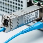
We reverted the flapping ports to optics that matched both the required Ethernet physical layer profile and the host’s documented compatibility list. Practically, that meant selecting 850 nm multimode SFP+ modules only for MMF runs that met the design reach class, and using 1310 nm single-mode SFP+ modules for the longer edge uplinks. The key change was that we stopped treating “form factor and speed” as sufficient and started treating optical network standards as the contract between host, module, and fiber.
For the corrected long uplinks, we deployed known-good 10GBASE-LR SFP+ transceivers with OS2 LC cabling, and for short/medium MMF links we used 10GBASE-SR SFP+ optics that were validated against the switch model. When we rebuilt the optics BOM, we also required DOM support that matched host polling behavior and ensured the modules reported stable transmit power and received power thresholds under load.
Implementation steps that prevented repeat failures
- Validate physical layer requirement: Confirm the intended Ethernet PHY profile (SR vs LR) and fiber grade assumptions against the actual cable plant.
- Check host compatibility: Use the switch vendor’s optics support matrix for the exact module family and vendor where required.
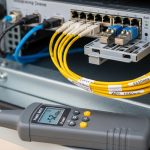
- Measure link budget: Use an optical power meter and light source to verify launch power and received power at the patch panel, then compare to the transceiver datasheet sensitivity.
- Confirm cleanliness: Inspect LC ends with a microscope and clean with lint-free wipes and approved cleaning film before insertion.
- Burn-in during maintenance window: Cycle the interface, monitor DOM stability, and verify no LOS/LOF events over a fixed observation window.
Pro Tip: Many “it should work” failures are not about total attenuation; they are about margin volatility. If received optical power hovers near the receiver sensitivity threshold, temperature swings and connector micro-contamination can push the link into LOS, causing flaps even when your static OTDR trace looks acceptable. Always validate received power with the exact transceiver in place, not just fiber loss.

Measured Results: What changed after standards-aligned optics
After the optics correction, we ran a controlled stability test on the previously flapping ports. Over a 72-hour observation window, the corrected links showed zero LOS events, and the interface counters stabilized with no recurring resets. Received power readings remained within a tight band, indicating consistent optical budget margin and reduced sensitivity to environmental variation.
We also measured operational improvements: the number of support tickets tied to link instability dropped, and mean time to repair decreased because the team stopped trial-and-error across module vendors. From a field-engineering perspective, the biggest win was predictability: once the mapping from optical network standards to SFP type (SR vs LR) matched the actual fiber, the system behaved deterministically.
Selection Criteria Checklist: How engineers choose SFP optics under optical network standards
When you are selecting SFP optics for a real deployment, use the following ordered checklist. This is the same sequence we used during the refresh because it aligns with both standards behavior and host practicalities.
- Distance and reach class: Confirm fiber length and expected reach for the exact fiber grade (OM3 vs OM4, OS2 vs legacy SMF).
- Standards profile fit: Choose optics aligned to the required Ethernet PHY (for example, SR at 850 nm or LR at 1310 nm) and not only the data rate.
- Switch compatibility: Verify the host model supports the module type and vendor family; some platforms enforce stricter transceiver signaling expectations.
- DOM support and thresholds: Ensure the module reports stable temperature, bias, transmit power, and receive power; confirm thresholds do not trigger alerts.
- Operating temperature: Use the datasheet temperature range; datacenter hotspots can push modules beyond comfort margins.
- Connector and fiber hygiene: Confirm LC type, polish grade, and cleaning procedures; contamination dominates failure rates in practice.
- Vendor lock-in risk: Balance OEM, authorized third-party, and open-market modules with warranty and support expectations.

Common Mistakes / Troubleshooting: How standards issues show up in the field
Below are concrete failure modes we have seen repeatedly when optical network standards requirements are inferred rather than verified.
LOS flaps after swapping “same speed” SFP+ modules
Root cause: The optics profile (SR vs LR) or launch/receive characteristics does not match the fiber plant and host expectations, leaving insufficient margin. Solution: Confirm the required PHY profile, then measure received optical power with the module installed; replace with optics that match the correct standards and reach class.
“Looks clean” fiber ends causing intermittent link drops
Root cause: Micro-contamination on LC connectors or damaged ferrules introduces high, time-varying loss. Solution: Inspect with a microscope, clean using approved methods, and re-test; do not rely on visual appearance alone.
DOM-triggered alarms even when the link is up
Root cause: A third-party module reports diagnostics slightly outside the host’s alert thresholds, or the host reads DOM fields differently than expected. Solution: Compare DOM telemetry against the module datasheet and host documentation; if necessary, switch to a module family validated for that platform.
Temperature-related instability in dense racks
Root cause: Modules operating near the edge of the temperature range can see bias drift that reduces receiver margin. Solution: Verify airflow, check ambient temperature near the transceiver cage, and select an optics variant with appropriate temperature rating.
Cost & ROI Note: Buying optics with realistic TCO
In many deployments, OEM optics carry a premium, while third-party modules can be cheaper upfront. Typical street pricing varies by vendor and volume, but a realistic budgeting range for 10G SFP+ commonly lands roughly in the $40 to $150 per module band depending on reach and authorization status; higher-speed generations can be meaningfully more expensive. The ROI lens should include failure rates, maintenance labor, and the cost of downtime during link instability events.
In our case, the corrected optics set cost more than the initial mixed-vendor plan, but it reduced troubleshooting time and eliminated recurring flaps. When you factor technician hours, incident escalation, and the operational cost of unstable aggregation uplinks, standards-aligned purchases typically pay back quickly.
FAQ: Optical network standards and SFP compatibility questions
Which optical network standards matter most for SFP links?
The practical ones are the Ethernet PHY profiles defined by IEEE 802.3 (for example, SR and LR variants) plus the host switch’s optics interface requirements. Always confirm the intended PHY profile and fiber grade, then validate module diagnostics behavior through DOM.
Can I use any 10G SR SFP+ module in my switch?
Not always. Even when the module is nominally 10GBASE-SR and uses LC connectors, the host may enforce compatibility for DOM signaling, thresholds, or vendor-specific behaviors. Check the switch vendor’s optics support matrix for your exact model.
How do I verify link budget before swapping optics?
Measure received optical power at the host end with an optical meter and compare it to the transceiver’s sensitivity and required margin. If possible, validate with the exact module you plan to deploy, because real-world launch power and receiver sensitivity can vary across vendors.
What is the fastest troubleshooting path for LOS errors?
Start with connector inspection and cleaning, then check transceiver DOM values for transmit power and received power. If those are inconsistent with expected values, swap to a known-good module type that matches the required optical network standards profile.
Are extended temperature SFP modules worth it?
If your racks have high ambient temperatures or restricted airflow, extended temperature variants can reduce instability and prolong reliability. Verify the module’s datasheet temperature range and ensure airflow meets vendor guidance.
Do third-party optics increase risk?
They can, depending on platform strictness and how well the module matches the host’s DOM expectations. With a rigorous compatibility checklist and proper link-budget verification, authorized third-party optics can be acceptable, but always validate before large-scale rollout.
Standards do not just describe theory; they define the boundaries that SFP transceivers must satisfy to deliver stable links. Your next step is to apply the checklist and verify reach-class alignment with the actual fiber plant using optical transceiver compatibility and DOM troubleshooting.
Author bio: I am a senior software and hardware engineer with 10+ years deploying and troubleshooting Ethernet optical links in production datacenters. I focus on practical standards compliance, optics selection, and field reliability measurements.