If you are planning a network refresh and want to avoid buying the wrong optics twice, this is for you. This article walks through practical optical module selection decisions for migrating from 10G to 25G and 100G, with real compatibility and troubleshooting notes from the field. You will get a specs comparison, a decision checklist, and common failure modes that usually show up during rollouts.
What changes when your network evolves from 10G to 100G?
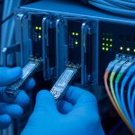
When you scale beyond 10G, the optics ecosystem shifts fast: different form factors (SFP+, SFP28, QSFP+, QSFP28), higher lane counts, and stricter signal budgets. IEEE 802.3 defines the Ethernet physical layer behaviors, but vendor implementations vary in DOM formats, power classes, and how aggressively they enforce compatibility checks. In practice, I have seen “it works on bench” turn into “link flaps in production” after temperature swings or when optics are paired with different switch PHY revisions.
For reference, common Ethernet PHY targets include 10GBASE-SR (short reach multimode), 25GBASE-SR (often multimode with new optics), and 100GBASE-SR4 (4 lanes over multimode). These align with IEEE 802.3 clauses for each speed tier, while the exact module performance depends on transceiver vendor datasheets and your cabling plant. If you need a baseline, start with IEEE 802.3 for the electrical/optical requirements and your switch vendor for supported part numbers. IEEE 802.3 standards

Key specifications that actually drive optical module selection
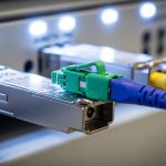
Most outages trace back to a mismatch in reach, fiber type, or electrical interface expectations. Before you pick a vendor, verify the wavelength, fiber mode (MMF vs SMF), connector type (LC vs MPO), and the temperature range you will run. Also check whether the switch expects a specific diagnostic interface (DOM) and whether it enforces “vendor validated” modules.
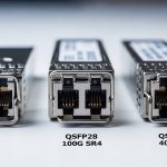
Specs comparison: 10G SR vs 25G SR vs 100G SR4
Here is a realistic comparison using widely deployed module families. Treat these as starting points; always confirm exact reach and power class in the vendor datasheet.
| Type | Wavelength | Fiber | Connector | Typical Reach | Data Rate | DOM | Operating Temp |
|---|---|---|---|---|---|---|---|
| SFP+ 10GBASE-SR | 850 nm | OM3/OM4 MMF | LC | ~300 m (OM3) / ~400 m (OM4) | 10.3125 Gbps | Usually yes (I2C) | 0 to 70 C typical |
| SFP28 25GBASE-SR | 850 nm | OM4 MMF | LC | ~100 m (common OM4 target) | 25.78125 Gbps | Usually yes | -5 to 70 C common |
| QSFP28 100GBASE-SR4 | 850 nm | OM4 MMF | MPO-12 | ~100 m (common OM4 target) | 103.125 Gbps | Usually yes | 0 to 70 C typical |
Concrete module examples engineers commonly reference
- Cisco SFP-10G-SR style 10G SR modules for LC multimode deployments.
- Finisar FTLX8571D3BCL class of 10G SR optics (vendor-specific naming varies by revision).
- FS.com SFP-10GSR-85 style optics for cost-focused 10G SR replacements.
Even when the wavelength and speed match, vendor DOM behavior and power class can differ. That is why switch vendor compatibility lists matter. For example, a switch may support “third-party SR modules” but only within certain power or temperature grades. FS.com product and datasheet references
Pro Tip: During pre-deploy testing, I recommend logging DOM readings (Tx bias current, laser power, and temperature) for at least 30 minutes while you gently ramp ambient temperature. If you see laser bias drift outside the vendor’s expected range, the “spec match” on paper is not enough for stable long-term links.
Deployment scenario: leaf-spine refresh in a real data center
In a 3-tier data center leaf-spine topology with 48-port 10G ToR switches and a planned upgrade to 25G aggregation, we mapped every uplink to a specific fiber bundle. We had OM4 multimode cabling with MPO trunks between row switches, and LC patch cords for short runs. The rollout plan used 10G SR on existing leaf uplinks (LC, 850 nm) and moved new server connections to 25G SR (LC, 850 nm) where the patch length stayed under the OM4 target. For spine upgrades to 100G, we selected 100GBASE-SR4 QSFP28 optics using MPO-12, keeping the MPO polarity and fiber lane mapping consistent with the splicing plan.
The key operational detail was that we validated link stability under load and checked that switch firmware reported DOM diagnostics consistently. One batch of “compatible” optics passed basic link bring-up but produced CRC spikes after 20 to 30 minutes at higher rack inlet temperatures. Swapping to a different vendor lot resolved it immediately, confirming that optics vendor revision behavior matters more than generic “SR is SR.”

Selection criteria checklist you can use before you click buy
Here is the ordered checklist I use for optical module selection in evolving markets:
- Distance and fiber type: verify OM3 vs OM4 vs OS2, patch cord length, and trunk length. Use your cabling test reports (including insertion loss and OM4 compliance).
- Correct Ethernet PHY: confirm the speed and standard (10GBASE-SR, 25GBASE-SR, 100GBASE-SR4) match what the switch ports support.
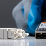
- Connector and polarity: LC duplex vs MPO-12 with correct polarity method (and consistent lane mapping) for SR4 optics.
- Switch compatibility and vendor validation: check the switch vendor’s optics list and firmware notes for third-party behavior.
- DOM support and monitoring: confirm DOM type (I2C) and that the switch reads temperature and laser bias without errors.
- Operating temperature grade: match your rack inlet range; optics derate differently across vendors.
- Vendor lock-in risk: if you must buy OEM for stability, plan a procurement strategy that avoids last-minute shortages.
- Power and thermal budget: ensure the module fits the switch’s power envelope and does not push thermal limits.
Common mistakes and troubleshooting tips
These are the failure modes I see most often when engineers revisit optical module selection under schedule pressure:
- Mistake: Buying “850 nm multimode” without confirming OM4 vs OM3 and actual link length.
Root cause: higher attenuation and modal bandwidth limits reduce signal margin.
Fix: check the cabling test results and shorten patch cords or move to OM4-capable optics. - Mistake: MPO polarity mismatch on SR4 links.
Root cause: lane swapping breaks the lane-to-lane mapping and causes high BER/CRC errors.
Fix: re-terminate using the documented polarity method and verify with an MPO polarity tester. - Mistake: Ignoring switch firmware and DOM quirks.
Root cause: some switch revisions treat certain DOM fields differently, causing intermittent link resets.
Fix: test optics on the exact switch firmware version and keep a known-good vendor lot for rollback. - Mistake: Not checking temperature behavior.
Root cause: laser bias and output power drift with ambient changes.
Fix: do a soak test in the actual rack airflow conditions and monitor DOM trends.
Cost and ROI note: OEM vs third-party optics
In many enterprise and mid-market rollouts, OEM optics can run roughly 1.5x to 3x the cost of third-party modules for the same nominal speed and reach. The hidden TCO is labor and downtime: if an optics batch causes intermittent errors, the cost becomes dominated by troubleshooting time, truck rolls, and risk to SLAs. Third-party optics can be a solid ROI when you validate DOM behavior, run burn-in tests, and maintain a compatibility matrix per switch model. If you are upgrading to 100G, treat the QSFP28 lane behavior and MPO handling as part of the total cost, not just the module price.

FAQ
Q: What should I verify first for optical module selection?
Start with fiber type and distance, then confirm the exact Ethernet PHY supported by the switch port. After that, check connector type and polarity requirements for MPO-based optics.
Q: Are DOM diagnostics required for stable operation?
Not always, but DOM is strongly recommended for monitoring and faster troubleshooting. Some switches will still bring up links without full diagnostics, but you lose visibility into laser power and temperature drift.