When a leaf-spine fabric starts throwing CRC errors, link flaps, or sudden high BER right after a patch-panel change, engineers need fast optical link troubleshooting that matches real cabling and transceiver behavior. This article helps data center operators, field service teams, and network engineers pinpoint whether the fault is in fiber, optics, or host configuration. You will also get a head-to-head comparison of the most common remediation paths—cleaning and polarity fixes, optics swaps, and configuration validation—so you can restore service with minimal downtime. Update date: 2026-05-01.
Patch-panel reality check: fiber path vs optics path
In high-density environments, most optical incidents are not “mystery RF” issues; they are deterministic failures in one of three places: the fiber link budget, the optical interface alignment/polishing, or the transceiver and switch optics configuration. Your first decision is whether you are dealing with a “light can’t get there” problem (loss, wrong fiber, bad connector) or a “light is there but signal quality is degraded” problem (dirty endfaces, marginal power, frequency drift, or incompatible optics settings). This distinction drives whether you start with power measurements and polarity verification or with cleaning and DOM-driven diagnostics.
How to classify the failure mode in minutes
Use switch telemetry to narrow scope before you touch anything physically. Typical indicators include: link up/down cycles (often polarity, wrong wavelength, or incompatible module), BER-related counters (dirty optics or marginal link), and optical receive power warnings (loss, dirty connectors, aging). If the link never comes up after a patch change, treat it as a routing and polarity issue first; if it comes up but degrades under traffic, treat it as an optical cleanliness and budget issue first.

Head-to-head: three troubleshooting paths that resolve most DC link faults
Engineers often debate whether to “clean first” or “measure first.” In practice, both are valid, but the best path depends on what the telemetry says. Below is a head-to-head comparison of the three most common remediation paths used in real deployments with 10G/25G/40G/100G optics.
Path A: Clean, inspect, and verify polarity
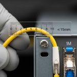
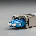
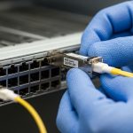
This path assumes the transceiver and wavelength are correct, and the issue is increased insertion loss or reduced extinction ratio due to contamination. It is especially effective after frequent moves: patching in dense racks, swapping pre-terminated trunks, or replacing patch cords. Field teams typically use a fiber inspection scope to check endfaces for dust, micro-scratches, and polymer residues, then clean with lint-free wipes and approved cleaning tools. Polarity verification is critical for duplex LC and MPO/MTP links; a single swapped strand can produce “link down” or severe BER.
Path B: Measure optical power and validate link budget
This path assumes the optics and polarity might be correct, but the link budget is out of spec due to excessive loss, an incorrect cable type, or an overly long run. You measure Tx optical power, Rx optical power, and compare against the transceiver’s receive sensitivity and the link’s expected attenuation. For multi-mode links using OM3/OM4, modal noise and insufficient launch conditions can also surface under higher-speed modulation.
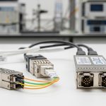
Path C: Swap optics and validate configuration/DOM behavior
This path assumes the optics themselves are marginal or incompatible with the host switch settings. You validate transceiver type, vendor compatibility, and optics settings (where supported), then compare DOM telemetry such as laser bias current, temperature, and optical output power against expected ranges from the module datasheet. In many modern switches, DOM thresholds also trigger alarms—use them as a forensic trail rather than a generic warning.
| Transceiver type (example) | Wavelength / rate | Typical reach | Connector | Power / diagnostics | Operating temperature | Where it helps most in troubleshooting |
|---|---|---|---|---|---|---|
| Cisco SFP-10G-SR | 850 nm / 10G | Up to 300 m (OM3) / 400 m (OM4) | LC duplex | DOM supported; Tx/Rx power telemetry | 0 to 70 C (module spec dependent) | Fast isolation when Rx power is low but link comes up intermittently |
| Finisar FTLX8571D3BCL | 850 nm / 10G | Up to 300 m (OM3) / 400 m (OM4) | LC duplex | DOM + vendor-specific thresholds | 0 to 70 C | Marginal link budget checks in dense patching environments |
| FS.com SFP-10GSR-85 | 850 nm / 10G | Up to 400 m (OM4) | LC duplex | DOM support; Tx bias and power | 0 to 70 C | Cost-effective swap testing to separate optics fault from cabling fault |
| Cisco QSFP-40G-SR4 | 850 nm / 40G | Up to 150 m (OM3) / 350 m (OM4) | MPO-12 (often) | DOM; lane-level behavior | 0 to 70 C | Lane polarity and MPO alignment issues during trunk replacement |
Key principle: IEEE 802.3 defines optical PHY behavior and BER measurement expectations, but the root cause in dense data centers is usually physical-layer loss or contamination rather than PHY logic. Use the standard as your boundary condition, not your diagnosis workflow. [Source: IEEE 802.3 Ethernet specifications]

Performance and reliability tradeoffs: what each path costs in downtime
Path A (clean/inspect/polarity) usually has the fastest mean time to repair when the issue is contamination or a recent patch change. Path B (measure budget) is slower because it requires calibrated power meters or switch telemetry plus careful accounting of patch cord loss, adapter loss, and splice loss. Path C (swap optics) can be quick if you have spares staged, but it can increase risk if you swap in optics that are not truly compatible with the host’s optics acceptance criteria.
Quantifying the impact with field numbers
In a typical 48-port ToR switch incident window, a “clean and retest” cycle might take 15 to 25 minutes including inspection under a scope. A full link budget measurement with a power meter and re-checking patch cord types often takes 45 to 90 minutes, especially if multiple lanes (for MPO) must be validated. A spare optics swap can be 10 to 20 minutes, but it shifts effort to procurement and compatibility verification if repeated swaps are needed.
Selection criteria checklist: choose the next action like an engineer
When you run optical link troubleshooting in production, the goal is to choose the smallest set of actions that maximizes probability of recovery. Use this ordered checklist to decide which path to execute first.
- Distance and expected reach: confirm your OM3/OM4/OS2 type and planned run length; compare to vendor reach claims with a margin for patch cords and adapters.
- Budget from telemetry: check Rx optical power alarms and DOM thresholds; treat “near sensitivity” links as candidates for cleaning before deeper swaps.
- Switch compatibility: verify the switch supports the optics type and speed; confirm whether it enforces vendor-specific optics acceptance.
- DOM support and alarm granularity: prefer modules with accessible DOM fields (laser bias current, temperature, Tx power, Rx power) to reduce guesswork.
- Operating temperature: validate module temperature and host airflow; elevated temperature can increase laser bias and degrade signal quality.
- Vendor lock-in risk: if you rely on OEM optics, model TCO including failure rates and lead times; keep a documented approved optics list.
Compatibility caveat: Third-party optics can work well, but some hosts are stricter about DOM values, EEPROM fields, or optical class. Always validate in a staging rack before broad rollout. [Source: Vendor transceiver acceptance and switch compatibility notes]
Common pitfalls and troubleshooting tips that prevent repeat outages
Below are concrete failure modes seen during optical link troubleshooting in dense data centers, along with likely root causes and fixes.
Pitfall 1: “Link down” after a patch change due to polarity or lane mismatch
Root cause: Duplex LC cables swapped A/B, or MPO/MTP trunks connected with reversed polarity or incorrect keying. For 40G/100G MPO, one lane mismatch can cause partial degradation or full link failure. Solution: verify polarity using the cable labeling scheme, then confirm MPO key orientation and lane mapping at both ends. Retest after each correction rather than making multiple changes at once.
Pitfall 2: Cleaning the wrong component or reintroducing dust
Root cause: technicians clean the connector exterior but not the fiber endface; or they use non-approved tools that leave residue. Even after cleaning, touching the ferrule or using a contaminated wipe can re-contaminate the surface. Solution: inspect with a scope before and after cleaning; use approved cleaning consumables and avoid any contact with the endface.
Pitfall 3: Treating low Rx power as “bad optics” without accounting for loss budget
Root cause: extra patch cords, additional adapters, or an unexpected connector type increases insertion loss beyond the transceiver’s receive sensitivity margin. In OM3/OM4, an incorrect fiber type or excessive loss can produce BER spikes under load. Solution: compute a loss budget including worst-case patch cord and adapter loss; measure Rx power and compare to the module datasheet limits.
Pitfall 4: Ignoring module temperature and airflow constraints
Root cause: crowded optics cages and blocked airflow can raise module temperature, increasing laser bias and reducing margin. This can show up as “works at idle, fails under traffic.” Solution: check DOM temperature alarms and verify airflow paths; reseat optics to ensure proper thermal contact and unblock front-to-back cooling.
Pro Tip: In many switch platforms, a “clean and reseat” that immediately restores link is not evidence that optics were bad; it often means the host’s optical connector interface cleared a micro-dust film on first contact. If DOM Tx/Rx power shifts by a measurable amount after reseating (for example, multiple dB), treat this as an endface cleanliness signal, not a random luck event.

Cost and ROI: OEM vs third-party optics and the economics of faster recovery
Price varies by data rate and reach, but realistic field ranges for common optics are often: 10G SR modules in the low tens to low hundreds of USD per unit (depending on vendor and compatibility), and 40G/100G modules can be several multiples higher due to higher lane complexity and stricter acceptance requirements. The ROI is not just purchase price; it is the cost of downtime, labor time, and repeat failures. OEM optics may reduce compatibility friction, but third-party optics can lower acquisition cost if you maintain a validated approved list and monitor failure rates.
Operationally, track: (1) mean time to repair, (2) number of swaps per incident, and (3) recurrence within 30 days. If you see repeat failures on the same rack rows, the issue is likely cabling hygiene, airflow, or labeling/polarity practices—not just a bad batch of optics. Model total cost of ownership (TCO) using your labor rate and typical restoration time. A one-hour outage for a busy tenant environment can dwarf the price difference between OEM and approved third-party optics.
Decision matrix: map your symptoms to the most likely winning option
Use this decision matrix during optical link troubleshooting to choose the next action. It is designed for dense deployments where time and access are limited.
| Observed symptom | Most likely root cause | Best first path | Second path (if unresolved) | Confidence trigger |
|---|---|---|---|---|
| Link never comes up after patch change | Polarity reversal or wrong lane mapping | Path A | Path B (confirm fiber type) or Path C (swap both ends) | LED/activity absent and no Rx power |
| Link up, but CRC/BER counters climb under traffic | Dirty endfaces or marginal link budget | Path A | Path B | Rx power near warning thresholds |
| Rx power alarm or large Rx drop after reseat | Connector contamination or adapter loss | Path A | Path B | Rx power changes by multiple dB after reseating |
| DOM alarms: high temperature or rising Tx bias | Thermal stress or optics aging | Path C | Path A (if coupled with recent moves) | DOM temperature correlated with errors |
| Intermittent link flaps during movement or airflow changes | Loose connector, blocked airflow, or micro-dust | Path A | Path C | Errors correlate with connector touch or rack airflow variation |
Which option should you choose?
If you manage high-density racks and your incident started after a patching or trunk replacement event, choose Path A first: clean, inspect, and verify polarity/lane mapping. If the link is up but performance degrades and DOM shows Rx power near thresholds, follow Path A then confirm with Path B using a real link budget. If DOM indicates thermal stress or your approved optics list conflicts with the installed module type, choose Path C early to isolate optics acceptance and aging.
Next step: build a repeatable workflow by standardizing how your team logs DOM readings, connector inspections, and loss budgets with optical transceiver compatibility.
FAQ
What should I check first during optical link troubleshooting?
Start with the symptom pattern: link down vs link up with errors. Then check switch telemetry for Rx power alarms, DOM temperature/bias, and error counters. If the change was recent and physical patching occurred, prioritize polarity and endface inspection before swapping optics.
Can dirty fiber endfaces cause link flaps or only high BER?
Both are possible. Dirty endfaces can reduce optical power enough to break receiver lock (causing flaps), or they can degrade signal quality enough to raise BER while the link remains technically “up.” Scope inspection and before/after Tx/Rx power comparison help confirm the mechanism.
How do I validate link budget without specialized test gear?
You can start with switch DOM Rx power and compare it to the module datasheet receive sensitivity and expected margin. Then account for known insertion loss from patch cords, adapters, and splices. For hard failures or disputes, a calibrated optical power meter and reference attenuators provide the most defensible measurement baseline.
Are third-party optics safe for production?
They can be, but only when they are validated with your specific switch model and optics acceptance behavior. Maintain an approved optics list, test in a staging rack, and monitor failure rates and DOM alarm frequency after deployment. OEM optics may reduce compatibility friction, but TCO depends on lead time and downtime costs.
What MPO/MTP polarity mistakes happen most often?
The most common issues are reversed polarity on one end and incorrect lane mapping due to trunk orientation or keying confusion. Always verify lane labeling and connector key orientation at both ends, and retest after each correction to avoid compounding variables.
When should I replace optics instead of re-cleaning?
Replace optics when DOM shows signs of aging or persistent out-of-range values after cleaning and polarity verification. Examples include repeatedly elevated laser bias current, abnormal temperature behavior, or consistent Rx power failure patterns across multiple cleaning cycles. Also replace if you have a spare that eliminates the issue quickly and repeatably.
Author bio: I design and audit data center optical workflows with a focus on reducing time-to-repair through interface-level diagnostics and UI-driven runbooks. Field-driven by deployments across leaf-spine fabrics, I translate vendor telemetry and IEEE PHY behavior into practical troubleshooting decisions.