Multi-cloud data centers fail in predictable ways: overspending on optics, underestimating reach and budget, and discovering compatibility gaps only after rollout. This article helps network and infrastructure engineers design and optimize optical infrastructure for multi-cloud connectivity with practical selection criteria, measurable operational checks, and vendor-neutral guidance. You will learn how to plan link budgets, choose transceivers that actually work with your switches, and troubleshoot the most common fiber and optics failures. Update date: 2026-05-01.

Why multi-cloud changes optical infrastructure requirements
When you add multiple cloud providers, your traffic patterns shift from steady north-south flows to more bursty east-west replication, backup, and migration workloads. That increases the number of active optical links, the number of transceivers in service, and the sensitivity to latency and error rates. Optical infrastructure must therefore be engineered for deterministic reach, power budget headroom, and operational manageability across many vendor combinations.
From a standards perspective, Ethernet optics are governed by IEEE 802.3 and the relevant optical interface specifications (for example, 10GBASE-SR, 25G/50G/100G short-reach families, and their PMD and coding profiles). In practice, the key is aligning your transceiver type and lane rate to the switch port configuration so that link training, FEC mode, and signaling parameters match. If you mix optics outside the intended profile, you may get link flaps, high BER, or complete link failure.
Operational design goals for multi-cloud
- Hit the reach target with margin: design for worst-case fiber loss, patching losses, and connector aging.
- Control optical power and thermal behavior: keep transceivers within their operating temperature and power ranges.
- Reduce change risk: prefer optics with documented compatibility and DOM telemetry support.
- Enable fast incident response: standardize labeling, cassette management, and test procedures.
Pro Tip: In multi-cloud environments, the biggest outage driver is rarely the transceiver itself; it is the patching path. Engineers commonly lose 1 to 3 dB in extra patch points and conservative connector assumptions, then later discover the remaining budget is too tight for aging fiber and higher-temperature operation. Build your link budget using measured loss per installed jumper, not spreadsheet averages.
Link budget and reach planning that survives real patching
Reach planning is where optical infrastructure projects either scale cleanly or stall during acceptance testing. You must translate “spec sheet reach” into “installed link margin” by accounting for fiber attenuation, connector and splice losses, and additional losses from MPO/MTP polarity handling, patch panels, and re-terminations. For SR-class multimode links, bandwidth and modal effects matter; for LR/ER-class single-mode links, the main risk is budget erosion from connector work and uneven cleaning.
A practical approach is to create a per-path link budget that reflects your actual cross-connect layout and expected number of moves, adds, and changes. Use OTDR or certified loss testing for acceptance, then store results with the circuit ID so future changes can be validated against historical baselines.
Technical specs comparison for common data-center optics
The table below compares typical short-reach multimode and long-reach single-mode options used in leaf-spine and multi-cloud interconnect designs. Always verify exact compatibility with your switch vendor’s transceiver matrix and firmware.
| Optical interface (example) | Wavelength | Typical reach class | Fiber type | Connector | DOM / telemetry | Operating temperature | Common use in multi-cloud DC |
|---|---|---|---|---|---|---|---|
| SFP-10G-SR (10GBASE-SR) | 850 nm | ~300 m typical | OM3/OM4 multimode | LC | Yes (industry standard; vendor varies) | 0 to 70 C typical | Legacy aggregation, short server uplinks |
| SFP+/QSFP+ 10/40G SR | 850 nm | ~100 m to 150 m typical | OM3/OM4 multimode | LC or MPO | Yes (verify) | 0 to 70 C typical | ToR and leaf-spine within a row |
| SFP-10G-SR or 10G SR transceiver example | 850 nm | Up to ~400 m class | OM4 multimode | LC | Yes | 0 to 70 C typical | Consolidated uplinks with patching margin |
| 100G QSFP28 SR4 (example) | ~850 nm | ~100 m typical | OM4 multimode | MPO/MTP | Yes (verify) | 0 to 70 C typical | High-density spine uplinks |
| 100G QSFP28 LR4 (example) | ~1310 nm | ~10 km class | Single-mode OS2 | LC | Yes | -5 to 70 C typical | Cross-bay and campus-like paths |
For concrete part examples commonly seen in deployments, engineers may reference modules such as Cisco SFP-10G-SR for 10G SR, Finisar FTLX8571D3BCL for 10G SR-class optics, or FS.com SFP-10GSR-85 for 10G multimode. Treat these as examples only; final selection must be validated against your switch model and optics compatibility list.

Link budget checklist engineers actually use
- Fiber attenuation: use the installed fiber type and measured route length.
- Connector loss: count every mated pair and include worst-case values from your acceptance standard.
- Splice and re-termination: add conservative margin if routes may be reworked.
- Patch panel and MPO handling: include extra loss for polarity management and cleaning variability.
- Power and receiver sensitivity: confirm transceiver receiver sensitivity and transmitter output per datasheet.
Transceiver selection: compatibility, DOM telemetry, and FEC
Choosing optics is not only about wavelength and reach; it is about how the module behaves with your specific switch ASIC, firmware, and line-side configuration. Multi-cloud data centers often standardize on a common switch family for ToR and spine, but interconnects may include different vendors, especially when connecting to cloud on-ramps or managed services.
Start by mapping each port speed to the correct optical interface type, then validate that the module supports the required signaling and any FEC profile used by the link. Many modern high-speed Ethernet links use FEC internally; if your transceiver does not match the expected behavior, you can see elevated error counts even when the link appears “up.”
Decision checklist for optical infrastructure procurement
- Distance and route variability: confirm measured worst-case length plus patching additions.
- Switch compatibility matrix: verify exact switch model, port type, and firmware version.
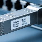
- DOM support and monitoring: ensure Digital Optical Monitoring provides reliable thresholds (Tx power, Rx power, bias current).
- Operating temperature and airflow: confirm module supports your rack inlet conditions; check switch airflow direction.
- DOM alarms and telemetry integration: confirm your monitoring stack can ingest alarms without alert fatigue.
- Budget and total cost: compare OEM vs third-party using installed failure rates and warranty terms.
- Vendor lock-in risk: ensure you can swap optics without requalification every time you replace a failed unit.
Pro Tip: If your monitoring only polls “link up/down,” you will miss degrading optics. In field practice, the earliest warning is drifting Tx bias and Rx power from DOM telemetry, often weeks before link errors spike. Configure thresholds and integrate them with incident tickets.
Multi-cloud topology patterns and where optics should be multimode vs single-mode
Typical multi-cloud data centers use a leaf-spine topology, sometimes with multiple fabrics for isolation. Within a row or within a building, multimode SR optics are often cost-effective due to lower per-fiber cost and simpler patching. For longer cross-connect routes, inter-building corridors, or higher-reliability single-path designs, single-mode LR optics reduce modal dispersion concerns and extend reach.
However, the best choice is not purely distance-based. It also depends on how often you expect to rework patch panels, whether you can enforce cleaning discipline, and how strictly you manage polarity for MPO-based cassettes. In multi-cloud setups, traffic bursts can cause transient congestion; if your optics are already near their sensitivity threshold, you may misdiagnose the issue as congestion rather than physical-layer impairment.
Guidance by distance and operational risk
- Short in-rack or same-row: consider multimode SR with strict patching control and measured loss validation.
- Across bays or longer corridors: consider single-mode LR to preserve margin and simplify acceptance testing.
- Inter-building or dark fiber: prefer single-mode and validate end-to-end OS2 cabling with certified measurements.

Common mistakes and troubleshooting steps for optical infrastructure
Most optics failures show up as “link down,” “CRC errors,” or periodic drops. The root causes usually fall into a few categories: budget miscalculation, poor cleaning, polarity mistakes, or transceiver compatibility issues. Below are concrete failure modes you can diagnose quickly with disciplined field steps.
Link up in the lab, fails after installation
Root cause: the installed patch path has more connectors and patch points than the design assumed, reducing received power below sensitivity. Sometimes the team also uses an optimistic “spec reach” rather than measured attenuation.
Solution: run certified loss testing end-to-end, then compare Rx power from DOM against expected ranges. If margin is insufficient, re-route to fewer patch panels or replace with a longer-reach interface class (for example, move from SR to LR where appropriate).
High error counters with stable link state
Root cause: FEC mode or signaling profile mismatch, or a marginal optical alignment/polish issue that does not fully break the link. Another common driver is transceiver behavior outside vendor-validated thresholds.
Solution: check switch optics logs for FEC and error metrics. Clean connectors using approved lint-free methods and confirm no scratches. If errors persist, swap to a known-compatible module from the switch’s matrix and re-test.
MPO polarity reversal after cassette replacement
Root cause: MPO/MTP polarity handling mistakes during maintenance. This can produce consistent but incorrect lane mapping, resulting in no link or intermittent flaps depending on link training.
Solution: verify polarity using a standard method (polarity reference method consistent with your cabling standard), then re-seat or flip the polarity adapter. Perform a controlled swap test using a known-good cassette before disturbing the entire path.
Thermal throttling in dense racks
Root cause: high-density optics installed in racks with insufficient airflow, pushing modules near their thermal limits. Some optics degrade gradually, showing rising bias current and falling Rx power.
Solution: measure rack inlet temperature and confirm it stays within module operating range. Adjust fan trays, verify baffles, and ensure switch airflow direction matches the module airflow path.
Cost and ROI considerations for multi-cloud optical infrastructure
Optics cost is only part of the total cost of ownership. Your TCO includes labor for replacements, downtime risk, testing time, and the cost of requalification when vendors or module types change. OEM optics often cost more per unit but may reduce compatibility risk and shorten incident resolution time.
In many deployments, third-party optics can be cost-effective if they are validated for your switch model and provide consistent DOM telemetry. A realistic budgeting view is to expect transceivers to vary widely by speed and reach: short-reach 10G SR modules may be inexpensive relative to 100G optics, while 100G LR optics and high-spec multimode modules typically dominate the optics spend. Use warranty length, return logistics, and failure rate history to compare total cost rather than only purchase price.
ROI improves when you standardize module types across fabrics, reduce truck-rolls through better telemetry, and avoid re-cabling by choosing the correct reach class early. In multi-cloud environments, reducing link incidents also protects higher-level service reliability and avoids escalations with cloud connectivity providers.
FAQ
How do I decide between multimode SR and single-mode LR for optical infrastructure?
Start with measured distance plus patching margin, then consider operational risk. If your installed path variability is high or you expect frequent rework, single-mode LR often preserves margin better. For short, stable in-building routes with disciplined patching and clean handling, multimode SR can be more cost-effective.
Do I need DOM support for monitoring in a multi-cloud data center?
Yes, DOM is strongly recommended because it provides early signals like Tx power, Rx power, and bias current drift. Monitoring link state alone will miss gradual degradation that leads to CRC or FEC-related errors. Ensure your switch and monitoring stack can read and alert on DOM thresholds.
What standards should I reference when planning Ethernet optics?
Use IEEE 802.3 for Ethernet optical interface definitions and PMD behavior. For cabling and installation practices, also align with recognized fiber cabling standards used in your region and your internal acceptance criteria. Vendor datasheets remain essential for receiver sensitivity, output power, and thermal specs.
Can I mix OEM and third-party optics to reduce costs?
You can, but you must validate compatibility on the exact switch model and firmware. Confirm DOM telemetry behavior and verify that the module supports the required signaling and any FEC expectations. Keep a controlled pilot group and measure error counters and DOM trends before broad rollout.
Why do I see link flaps after a maintenance window?
Common causes are connector contamination, polarity mistakes on MPO cassettes, and re-seating optics that are not fully latched. Another frequent issue is accidental patching into the wrong cross-connect. Use certified loss tests and DOM telemetry to confirm whether the impairment is optical power related or configuration related.
What is the fastest troubleshooting workflow for optics?
First, check switch logs for optics alarms, FEC mode, and error counters. Then verify DOM values (Tx bias, Tx power, Rx power) and inspect/clean connectors using an approved method. If values are inconsistent or polarity is suspect, perform a controlled swap with a known-good module or cassette and re-test.
Optimizing optical infrastructure for multi-cloud data centers is about engineering installed margin, enforcing compatibility, and turning DOM telemetry into actionable operations. If you want a follow-on topic, review optical fiber cabling standards and acceptance testing to strengthen your acceptance and maintenance process.
Author bio: I have deployed and troubleshot high-density Ethernet optics in multi-tier data centers, including link-budget validation with certified test results and DOM-driven incident response. I focus on practical alignment between IEEE interface requirements, vendor transceiver behavior, and real-world patching workflows.