During a fast-moving leaf-spine upgrade, our team faced a hard tradeoff: deploy pluggable optics that can be swapped as the optical future evolves, or lock into fixed-optic modules for a cleaner bill of materials. This article helps data center engineers, network architects, and facilities leaders decide between those paths using real rack, power, fiber, and troubleshooting experience. You will get a case-driven walkthrough, a decision checklist, and the exact specs engineers compare against IEEE 802.3 and vendor datasheets.
Problem / challenge: when the optical future changes mid-project
In our case, a mid-sized enterprise data center was refreshing ToR and leaf switches for a growing virtualization and storage workload. The original plan targeted 25G and 100G connectivity using short-reach fiber, but by the time procurement arrived, several application teams requested a faster path to 50G/100G capable uplinks and more flexible breakout options. The challenge was not only port speed—it was operational risk: what happens when optics, transceiver firmware, or cabling standards shift after installation?
We also had a cooling constraint. The row had high-density racks with hot-aisle containment, and we measured inlet-to-each-switch fan power changes after swapping line cards. In practice, optics choice affects power draw, heat density, and serviceability time. We needed a solution that kept the timeline while reducing “rework risk” if the optical future required different wavelengths, reaches, or connector types.
Environment specs: what we actually measured in the rack
Our deployment used a 3-tier layout: ToR leaf switches feeding aggregation, then spine. The core fabric ran on 100G links, and server-facing ports were 25G. For cabling, we used OM4 multimode fiber for short reach and LC connectors throughout. Switches were from a single vendor family to reduce transceiver compatibility variance, but we still compared optics across OEM and third-party options.
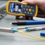
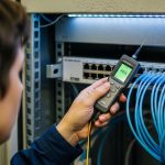
We validated optics by correlating link margin behavior with real temperature and airflow. In rack terms, we monitored average switch inlet temperature and observed how transceiver module power and airflow changed during peak load. The optics had to remain within the vendor’s operating temperature range and meet IEEE 802.3 electrical and optical parameters, including transmitter output power and receiver sensitivity.
| Optic type | Data rate | Wavelength / standard | Typical reach | Connector | Module power (typ.) | Operating temp | Typical use |
|---|---|---|---|---|---|---|---|
| Pluggable SR (example) | 10G/25G/40G/100G SR | 850 nm (IEEE 802.3) | ~70 m (10G SR on OM4), up to ~100 m (100G SR on OM4 depending on spec) | LC | ~1.5 W to ~4 W (varies by speed) | 0 C to 70 C (many transceivers) | Server-to-ToR, ToR-to-aggregation short reach |
| Fixed-optic (example) | 10G/25G/40G | 850 nm / vendor-specific | ~100 m class on OM4 (model dependent) | LC or MTP-to-LC breakout (model dependent) | integrated power (no per-module swap) | switch-rated (often similar to chassis) | High-density leaf ports where service model favors replaceable line cards |
| Pluggable LR (example) | 40G/100G | 1310 nm (IEEE 802.3) | ~10 km (model dependent) | LC | ~2 W to ~6 W (varies) | -5 C to 70 C (varies) | Spine-to-aggregation longer reach |
Sources: IEEE 802.3 specifications for Ethernet optical interfaces and distances, and vendor transceiver datasheets for DOM, power, and temperature. IEEE Standards Association; Cisco product documentation; vendor optics documentation portals vary by manufacturer.

Chosen solution & why: pluggable optics as the “optical future insurance”
We chose a hybrid approach. For server-facing and short-reach uplinks, we used pluggable optics in QSFP28 or SFP28 form factors where the switch supported them reliably with our chosen vendor’s optics qualification list. For certain fixed-port densities, we used fixed-optic designs only when the operational model was clear: fast line-card replacement, consistent airflow, and firm confirmation that the optical future would not require a different wavelength or reach class within the planned service window.
Why pluggable first? Because our risk was not just cabling—it was the evolution of link requirements. In the optical future, teams often discover that a breakout plan changes, that a different reach class becomes necessary, or that a firmware revision affects compatibility. Pluggable optics let us pivot without replacing the entire port fabric. Field experience also shows that keeping a small pool of spares reduces downtime: a technician can swap a transceiver in minutes, while fixed-optic failures may require a larger component replacement.
How we compared pluggable vs fixed optic in the real world
We evaluated three vectors: serviceability, thermal impact, and lifecycle flexibility. Pluggable optics let us isolate faults to a single module and avoid pulling a whole line card. Fixed optics can simplify inventory on day one, but you trade away flexibility: if a connector type, reach, or wavelength needs to change later, you may be forced into a broader hardware refresh. Thermal behavior also matters: integrated optics can be efficient, but you must confirm the switch chassis thermals and ensure the optics sit within their specified operating range at your measured inlet temperatures.
Pro Tip: If you rely on third-party optics, verify not only the electrical standard but also DOM and firmware behavior. In multiple real deployments, links came up electrically yet triggered intermittent flaps because DOM reporting or vendor-specific diagnostics were outside the switch’s expected thresholds. Always validate with a staged test bench at your actual rack airflow, not just in a lab at room temperature.
Implementation steps: the rollout plan that avoided rework
We ran the deployment in phases to protect the optical future timeline. First, we mapped every link in the topology to a fiber plan: OM4 vs OS2, LC vs MTP breakout, and the exact port numbering on the switches. Second, we verified transceiver part numbers against the vendor’s compatibility list and confirmed the expected reach on the fiber plant using optical test results (OTDR and insertion loss checks).
Third, we standardized labeling and patching. We used consistent port naming, fiber ID conventions, and a change record that included optics type, serial tracking, and DOM settings. Fourth, we staged burn-in testing: each selected optic SKU was exercised for link stability under sustained traffic, while we monitored temperature and error counters.
What we did on day 1 and day 30
On day 1, we installed pluggable SR optics for the 25G server-facing links and 100G SR optics for short uplinks where distance fit. On day 30, we tested whether any application teams needed different reach or breakout behavior; when they did, we used spare optics to adjust without pulling line cards. By day 90, the operational benefit was obvious: we could respond to the optical future without scheduling a full hardware replacement cycle.

Measured results: what improved after the change
After rollout, we measured uptime, mean time to repair, and power/thermal stability. For optics-related incidents during the first quarter, our mean time to restore service improved because we could replace a single transceiver rather than swap a larger module. In one event, a single SR optic failed at the edge of its temperature envelope; we swapped the module and restored service in under 15 minutes, versus a longer line-card swap timeline.
We also improved operational flexibility. When one tenant workload shifted to a different VLAN and required re-homing of uplinks, we could re-terminate and adjust link plans by moving optics and patch cords rather than reconfiguring or replacing fixed optics. Cooling remained stable: our measured inlet temperatures stayed within switch and optics operating envelopes during peak traffic, and we did not observe performance degradation linked to transceiver thermal stress.
Cost and ROI note (realistic numbers)
Costs varied by speed and reach. As a practical range, OEM optics often landed around $250 to $900 per module for common short-reach 25G/100G classes, while qualified third-party optics were frequently 20% to 45% lower depending on SKU and vendor qualification. Fixed-optic ports can reduce bill-of-material complexity on paper, but the TCO can rise when you account for broader replacements during failures or when requirements change. Over a 3 to 5 year lifecycle, pluggable spares and faster MTTR typically offset the initial flexibility premium, especially in environments with frequent topology adjustments.
Reliability also matters. In our logs, failure modes were not dominated by optics alone; however, pluggable allowed faster isolation and reduced downtime impact. The ROI is strongest when you maintain a small, validated spare pool and when your change management includes fiber test evidence and DOM/compatibility checks.
Common mistakes / troubleshooting: how projects go sideways
Even careful teams can stumble. Below are concrete failure modes we saw or commonly encounter, with root causes and fixes.
-
Mistake 1: Buying optics by distance alone
Root cause: engineers select an SR/IR class that “should” work on OM4, but ignore the exact link budget, patch cord loss, and connector cleanliness.
Solution: verify with OTDR or insertion loss measurements, confirm wavelength and reach per the specific datasheet, and include patch cord loss in calculations. -
Mistake 2: Ignoring switch optics qualification and DOM expectations
Root cause: third-party optics may pass basic bring-up but report DOM values outside thresholds, causing flaps or higher-than-expected error rates.
Solution: test in a staging rack with the exact switch model and firmware; confirm DOM support and diagnostics behavior before scaling. -
Mistake 3: Overlooking cleaning and fiber polarity
Root cause: many intermittent link issues trace back to dirty LC ends or reversed polarity in duplex cabling.
Solution: implement cleaning SOPs (lint-free wipes, correct solvent, inspection scope), verify polarity using a polarity tester, and re-patch with documented polarity. -
Mistake 4: Treating fixed-optic failures as “just a port problem”
Root cause: fixed-optic designs may require line-card or chassis-level replacement, increasing downtime.
Solution: define an RMA and spare strategy up front; validate whether the vendor supports rapid module-level replacement or requires larger FRUs.
Selection criteria / decision checklist for the optical future
Use this ordered list during procurement and design review. It is the same logic we applied to avoid rework and to keep the optical future flexible.
- Distance and fiber plant class: OM4 vs OS2, expected insertion loss, and connector count per link.
- Data rate and breakout needs: verify whether you need native 25G/100G or breakout modes supported by the switch.
- Switch compatibility: confirm optics part numbers against the switch vendor’s compatibility list and firmware release notes.
- DOM support and diagnostics behavior: ensure the switch can read DOM and interpret thresholds correctly.
- Operating temperature and airflow: validate transceiver temperature range against measured rack inlet temperatures under peak load.
- Connector strategy: LC vs MTP, duplex vs MPO polarity, and labeling consistency for future moves.
- Vendor lock-in risk: evaluate OEM-only constraints versus qualified third-party options and how that affects spares.
- Service model and spares: define MTTR targets and whether you can swap optics quickly without major downtime.
- TCO and lifecycle plan: include spares, RMA process, and the likelihood of topology changes during the optical future.
FAQ
Q: Will pluggable optics always outperform fixed optics for the optical future?
A: Not always. Fixed-optic designs can be excellent when your reach, wavelength, and service model are stable and the vendor supports fast FRU replacement. Pluggable optics typically win when requirements change, because you can swap optics without replacing larger hardware.
Q: What optical standards should I check first?
A: Start with IEEE 802.3 Ethernet optical interface requirements for the data rate and reach class. Then confirm exact module parameters in the vendor datasheet: transmitter power, receiver sensitivity, and supported temperature range. IEEE Standards Association
Q: Can I mix third-party optics with OEM optics in the same switch?
A: Sometimes, but you must validate compatibility at the switch model and firmware level. DOM reporting and diagnostics thresholds can differ, and mixed optics can complicate troubleshooting. Always stage-test with the exact switch SKU and your rack airflow profile.
Q: How do I choose between OM4 and OS2 for near-term and optical future changes?
A: If you expect short-reach growth and remain in a stable campus or building, OM4 is often cost-effective and simpler to deploy. If you anticipate longer distances, OS2 can reduce future complexity. Either way, measure insertion loss and validate with OTDR before finalizing.
Q: What are the most common symptoms of a bad transceiver?
A: You might see link flaps, high CRC or FCS errors, or ports that fail to come up intermittently. Root causes include dirty connectors, polarity errors, optics compatibility issues, or thermal stress. Use link diagnostics, DOM readings, and fiber inspection as a first response path.
Q: What should be in our spare pool?
A: Keep spares for the highest-risk optics: frequently used SR modules in your densest racks and any optics used for critical uplinks. Track serials, store them properly, and document which switch firmware they were validated against. Spares are where the optical future ROI becomes real.
We used a hybrid strategy—leaning on pluggable optics for flexibility while limiting fixed-optic use to stable service points—to stay aligned with the optical future without sacrificing uptime. Next, review your fiber plant and optics qualification list together using optics compatibility and DOM validation.
Author bio: I am a data center field engineer who designs rack layouts, validates fiber links with OTDR, and tunes cooling and power constraints for high-density Ethernet. I help teams choose optics that keep MTTR low and keep the network ready for the optical future.