If your data center has hit the “too many transceivers, too many RMA tickets” stage, you are not alone. This article compares an on-board optics transceiver approach with traditional pluggable optics for engineers, architects, and operators planning upgrades or new leaf-spine builds. You will get practical specs, compatibility gotchas, and a decision checklist you can actually run during procurement and commissioning.
Head-to-head: performance and signal reach in real networks
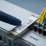
Both on-board optics transceiver and pluggable optics can deliver IEEE 802.3-compliant Ethernet over fiber, but the implementation style changes what you can optimize. On-board optics typically integrates the optical engine and sometimes part of the optical/electrical path directly onto the switch or NIC PCB, reducing interconnect complexity. Pluggable modules (SFP, SFP+, QSFP, OSFP, and cousins) keep the optical part in a removable “cartridge,” making it easier to swap reach and wavelength options.
What “performance” really means during commissioning
In the field, “performance” is usually a bundle of: link stability, BER margin, latency consistency, and how quickly you can validate optics after a swap. For example, in a leaf-spine fabric using 25G or 100G Ethernet, engineers care about whether the module supports the same lane mapping and whether the optic stays within optical power and receiver sensitivity targets over temperature. With on-board optics, you avoid module-to-module variation, but you also lose some of the flexibility to choose a different reach SKU without replacing the whole line card or board.
Specs snapshot: common Ethernet optics classes
Below is a representative comparison of typical options you might see in data centers. Exact values vary by vendor and exact part number, so always confirm against the specific datasheet.
| Optics approach | Typical form factor | Data rate | Wavelength | Connector | Reach (typical) | Operating temperature | Power budget impact |
|---|---|---|---|---|---|---|---|
| On-board optics transceiver | Integrated on switch PCB | 25G/50G/100G Ethernet | 850 nm (SR) or 1310 nm (LR) | Often LC or MPO internal to chassis | SR: tens of meters; LR: kilometers (model dependent) | Vendor-specific; often industrial ranges | Lower external module overhead; still depends on line card |
| Pluggable optics | SFP+ / QSFP28 / OSFP | 10G to 400G (varies) | 850/1310/1550 nm | LC or MPO/MTP | SR: 70 m to 300 m (SKU dependent); LR: up to 10 km+ | Commercial or extended; often 0 to 70 C or -5 to 85 C | Module power varies; line card budget must match |
For standards context, Ethernet over fiber behavior is defined by IEEE 802.3 (including PCS/PMA behavior and optical link requirements) while module management is commonly handled through vendor and industry digital interfaces. For the “how links should behave” baseline, see IEEE 802.3 standard. For transceiver management concepts, vendors commonly implement digital diagnostics per industry patterns documented in transceiver standards and vendor application notes; a good starting point is SFF Committee resources.
Pro Tip: During bring-up, do not judge optics quality by “it links.” Validate optical power levels and receive margin using the switch CLI and the module’s digital diagnostics (DOM or vendor equivalent). A pluggable optic can show “in spec” at room temperature but fail marginally at the top of the operating range; on-board optics tends to be more consistent because the optical path and calibration are fixed per board design.
In short: on-board optics can be more consistent and sometimes slightly more efficient because it reduces module-to-host interconnect variability. Pluggable optics can be more adaptable because you can swap reach, wavelength, and vendor options without board-level changes.

Cost and TCO: where the money actually moves
Cost comparisons often go wrong because people compare the module price and ignore operational costs. Total cost of ownership (TCO) includes spares strategy, RMA turnaround time, downtime during maintenance windows, and labor hours for swaps. Pluggable optics can reduce board downtime because you replace a module rather than an entire line card. On-board optics can reduce the number of “things to misplace,” but when something fails you might pay with a bigger replacement unit.
Typical pricing reality (ballpark ranges)
Street pricing depends on speed, reach, and whether you buy OEM or third-party. As a rough planning range, third-party pluggable optics for common 10G/25G/100G SR links might be priced significantly below OEM, but compatibility risk and warranty terms can erode those savings. OEM modules for mainstream platforms can cost more per unit, yet they often come with better documentation and fewer support escalations.
On-board optics is not usually purchased as a standalone line item because it is integrated. The “cost” shows up as higher upfront hardware cost for the chassis or line card design, offset by fewer external modules and potentially lower power overhead per port. However, if you need additional reach support later, pluggable optics usually wins because you can buy the right SKU without redesigning the fabric.
Power and cooling: small differences add up at scale
Even small power deltas matter when you are running thousands of ports. Pluggable modules consume power and contribute to thermal load at the port area; the line card and chassis must allocate thermal headroom. On-board optics can sometimes improve power efficiency by optimizing the electrical and thermal design for the fixed optic type, but you still must confirm the platform’s thermal design limits and airflow requirements in the vendor hardware guide.
For budgeting, track: (1) number of ports, (2) expected optics mix (SR vs LR), (3) predicted annual failure rate and mean time to repair, and (4) spares inventory holding costs. OEM vs third-party decisions should include warranty and return shipping terms, not just sticker price.

Compatibility and operations: swaps, firmware, and platform lock-in
This is where the “future” argument gets spicy. Pluggable optics typically support a broader ecosystem of vendors and reach types, but compatibility depends on the switch platform’s acceptance list, firmware expectations, and sometimes the digital diagnostics format. On-board optics is usually platform-specific by definition: you buy the switch line card with a fixed optic design and you follow the vendor’s supported fiber and connector plan.
DOM and diagnostics: the practical difference
Many pluggable optics expose digital diagnostics (DOM) such as laser bias current, optical output power, and temperature. Switch platforms use that telemetry for alarms and quality monitoring. On-board optics may expose similar telemetry through the platform’s management interface, but the exact fields and thresholds are vendor-specific.
Firmware and acceptance behavior
During change control, pluggable optics can introduce surprises: some platforms enforce vendor-specific optic IDs, some require firmware that recognizes the module’s data format, and some platforms are picky about lane mapping. On-board optics reduces that class of problem because the optic is designed and validated as part of the board.
For standards-minded engineers, the fiber link itself is governed by IEEE 802.3 physical layer behavior, but management and module interoperability are governed by SFF committee practices and vendor implementations. Always validate with the exact switch model and optic part number combination, using the vendor compatibility matrix.
Decision matrix: which option helps your constraints?
Use this matrix as a quick filter. Score each category as Low/Medium/High based on your environment.
| Factor | On-board optics transceiver | Pluggable optics |
|---|---|---|
| Multi-reach flexibility (SR vs LR) | Low: board/line card change often required | High: swap module SKUs |
| Operational consistency | High: fixed calibration per design | Medium: module variation across vendors |
| Maintenance speed | Medium/Low: may require line card replacement | High: replace optic only |
| Spare inventory complexity | Medium: fewer module spares, more board spares | Medium/High: track multiple optic SKUs |
| Vendor lock-in risk | High: platform and board design specific | Medium: depends on acceptance lists and DOM |
| Upfront CAPEX | Often higher per chassis/line card | Often lower upfront per port |
| Thermal/power efficiency opportunity | Medium/High: optimized integration possible | Medium: depends on module and airflow |
Framework note, because management consultants are required to be dramatic: this matrix is not a prophecy, it is a tool to reduce decision entropy. Your actual outcome depends on your platform’s documented support model and your operational processes.
Selection criteria checklist: what to verify before buying
Here is the ordered checklist engineers and procurement teams should run when choosing between an on-board optics transceiver design and pluggable optics. Treat it like a pre-flight inspection, not a wish list.
- Distance and link budget: confirm fiber type (OM3/OM4/OS2), expected attenuation, and connector losses. Validate against the platform’s supported reach for the exact optic class.
- Switch compatibility: verify the exact switch model and line card SKU supports the optic type. For pluggables, check the vendor compatibility matrix and acceptance rules.
- DOM and monitoring: confirm which diagnostics are exposed and what thresholds trigger alarms. Ensure monitoring integrates with your NMS and alerting workflows.
- Operating temperature and thermal design: check the module or board temperature range and chassis airflow recommendations. If you run near the top of spec, plan for higher optical power margin requirements.
- Wavelength and connector standard: LC vs MPO/MTP matters for patch panels. Make sure your fiber plant uses the connector style the optic expects.
- Vendor lock-in risk and warranty terms: for on-board optics, replacement is typically board-level. For pluggables, warranty and RMA handling can differ by OEM vs third-party.
- Spare strategy: decide whether you stock modules (pluggable) or line cards/chassis components (on-board). Model downtime cost during maintenance windows.
- Roadmap and reach changes: if you expect future shifts (for example, 100G SR to 100G LR), pluggables usually reduce rework costs.
Real deployment note: in a multi-tenant colocation facility, you often inherit patching constraints and mixed cabling. In that environment, pluggables can be a lifesaver because you can match the optic reach to the existing fiber plant without touching the entire chassis architecture.

Common mistakes and troubleshooting: how optics projects faceplant
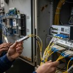
Even experienced teams get burned. Here are concrete failure modes, their likely root causes, and what to do next when the link goes from “green” to “why is it blinking like that.”
Wrong fiber type or patch panel mismatch
Root cause: using OS2 single-mode fiber where an SR multimode optic was expected, or mixing OM3/OM4 assumptions with incorrect patch cord lengths. Connector polarity or lane mapping errors with MPO/MTP also cause intermittent links.
Solution: verify fiber type and attenuation using OTDR or at least measured link loss. For MPO, confirm polarity method (for example, MTP cassette polarity scheme) and re-terminate or re-patch to match the platform’s expected polarity handling.
Overlooking DOM alarms and receiver power margin
Root cause: “Link up” hides marginal receiver conditions. Laser aging, dust on connectors, or cold/warm temperature drift can push the link toward failure thresholds.
Solution: check DOM/telemetry for receive power, transmit power, and temperature. Clean connectors using proper lint-free wipes and isopropyl alcohol procedures; re-seat the optic and re-measure. If your platform supports it, confirm the negotiated mode matches expectations (for example, lane alignment and FEC behavior when applicable).
Using unsupported third-party pluggables
Root cause: acceptance lists, firmware compatibility, or DOM data formatting differences. Some optics may be electrically compatible but fail management expectations, causing flaps or disabled ports.
Solution: use optics that are explicitly validated for your switch model and firmware version. If you must test third-party, run a controlled pilot: limited ports, stable patching, and monitoring for alarm patterns over 24 to 72 hours across temperature variations.
Ignoring thermal headroom on high-density ports
Root cause: airflow bypass, blocked vents, or dense stacking that raises line card temperature. Pluggables and on-board optics both suffer, but integrated designs may have different thermal distribution.
Solution: verify chassis airflow direction, clear baffles, and check temperature sensors in the line card. If you see repeated optic temperature alarms, adjust airflow or re-balance port density.
In the field, troubleshooting is rarely one problem; it is a chain. Fix the fiber plant and the optics cleanliness first, then validate compatibility and thermal conditions.
Which Option Should You Choose?
Here is the clear recommendation by reader type, with minimal hand-waving and maximal reality.
- If you run a stable, standardized fabric with predictable optics needs: choose on-board optics transceiver when the platform vendor offers strong diagnostics and you are comfortable with board-level spares. You will likely get consistent behavior and fewer “module identity” headaches.
- If you operate mixed cabling plants, frequent moves, and reach changes: choose pluggable optics. The ability to swap SR vs LR optics without board replacement usually reduces downtime and lowers rework costs.
- If you are optimizing maintenance speed during outages: pluggables are usually easier to recover because a technician can replace a failed module instead of replacing a line card.
- If you are optimizing long-term standardization and reducing operational variance: on-board optics can be attractive, especially when your operations team prefers “fewer SKUs, fewer variables.”
Next step: map your requirements to the checklist above, then validate with the exact switch model and optics part numbers against the vendor documentation. If you want more on how optics choices relate to cabling design, see fiber cabling design for data centers.
FAQ
What is an on-board optics transceiver compared to a pluggable module?
An on-board optics transceiver integrates the optical engine into the switch or NIC hardware so there is no removable optic cartridge for that port. A pluggable module uses standardized form factors so you can swap optics (for example, different reach SKUs) without replacing the line card.
Will on-board optics reduce link failures?
It can reduce certain failure modes related to module variance and interconnect differences, because the design is fixed per board. However, link failures from fiber plant issues, connector contamination, and thermal problems can still happen with both approaches.
Can I use third-party pluggable optics on enterprise switches?
Sometimes, but not safely by default. You must check the platform’s compatibility matrix and firmware requirements, and you should run a pilot before scaling. Otherwise you risk port flaps, disabled diagnostics, or management incompatibility.
Do both options use IEEE 802.3 Ethernet standards?
Yes, the Ethernet physical layer behavior is governed by IEEE 802.3 for the relevant data rate and interface class. The main difference is how optics are packaged and managed rather than whether Ethernet compliance exists.
How should I plan spares for on-board optics?
Plan for board-level or chassis-level spares, depending on vendor design. You will typically stock spare line cards rather than individual optics, which changes your warehouse strategy and downtime planning.
What is the fastest troubleshooting approach when a port does not pass traffic?
Start with fiber verification (type, polarity, connector cleanliness, and measured loss). Then validate optics diagnostics (DOM or platform telemetry) and finally confirm compatibility and thermal conditions for the exact hardware and firmware combination.
Author bio: I have deployed Ethernet optics in production data centers, including link bring-up, DOM alarm tuning, and RMA-driven spares planning for high-density switch fabrics. I write like a field engineer: measured values, vendor datasheet alignment, and fewer “it should work” assumptions.