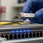
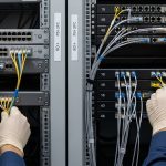
When an OmniSwitch running Alcatel-Lucent AOS starts showing “unsupported transceiver” alarms, the root cause is usually not fiber loss alone. It is often an optics/DOM mismatch, vendor EEPROM behavior, or a transceiver type that is electrically compatible but not AOS-qualified. This reference helps data center engineers select and validate Nokia Enterprise SFP modules for OmniSwitch AOS in day-to-day operations, including rack-level power, fiber handling, and troubleshooting steps.
Why OmniSwitch AOS is picky about SFP EEPROM and DOM data
In practice, OmniSwitch AOS ports do more than check link training; they validate transceiver identity via the SFP’s EEPROM fields and monitor DOM telemetry. Most enterprises deploy a mix of OEM and third-party optics, but AOS behavior varies by platform, software release, and the port’s SFP profile. If the transceiver reports out-of-range diagnostics (for example, vendor-specific scaling of temperature or bias current), AOS can flag the module even when the optics are physically functional. For engineers, the fastest path is to treat the module as an electrical + management object, not just a light source.
What AOS typically validates
During insertion, the switch reads EEPROM parameters such as vendor OUI, part number, nominal wavelength, encoding (typically 10GBASE-SR), and supported DOM thresholds. Then it polls for live DOM values and compares them to expected ranges or sanity checks. Some OmniSwitch AOS builds are strict about the transceiver “type” byte and the DOM compliance fields, which can differ across vendors even for the same nominal spec. Confirm the platform’s SFP type (for example, SFP for 1G vs SFP+ for 10G) before you chase fiber issues.
Pro Tip: If AOS logs show “transceiver not supported” immediately after insertion, check EEPROM identity mismatches first (DOM and part-number fields) before running optical power tests. I have seen cases where optics passed a cable plant OTDR test but still failed AOS because the module’s EEPROM type field did not match the port profile.

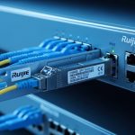
Key Nokia Enterprise SFP optics specs for OmniSwitch AOS port planning
OmniSwitch AOS compatibility depends on correct optics type: wavelength, data rate, encoding, and reach class. Engineers often standardize on 850 nm multimode for short-reach and 1310 nm single-mode for longer runs, but the AOS port must match the expected profile. Below is a practical comparison for the most common SFP families you will see in enterprise ToR and aggregation designs.
Quick spec comparison for common SFP use-cases
| Module profile | Nominal wavelength | Typical reach | Fiber type | Connector | DOM behavior | Operating temperature |
|---|---|---|---|---|---|---|
| SFP 1GBASE-SX | 850 nm | Up to 550 m (OM2) / 300 m (OM1) | MMF | LC | Standard digital DOM | 0 to 70 C typical (vendor dependent) |
| SFP+ 10GBASE-SR | 850 nm | Up to 300 m (OM3) / 400 m (OM4) | MMF | LC | Standard digital DOM | -5 to 70 C typical (vendor dependent) |
| SFP 10GBASE-LR | 1310 nm | Up to 10 km | SMF | LC | Standard digital DOM | -5 to 70 C typical |
| Nokia Enterprise SFP (portfolio varies) | Depends on SKU | Depends on SKU | MMF or SMF | LC (most common) | DOM supported on qualified SKUs | Depends on industrial grade vs standard |
Use this table as a sanity check before you touch AOS settings. If your OmniSwitch port expects a specific encoding and data rate, a mismatched transceiver can appear “inserted” but remain in an error state. IEEE 802.3 defines link layer behavior, while vendor datasheets define the exact electrical and optical parameters your switch will see. [Source: IEEE 802.3 (relevant 1GBASE-SX, 10GBASE-SR, 10GBASE-LR clauses)]
Validation workflow: matching Nokia Enterprise SFP to OmniSwitch AOS
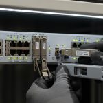
Engineers need a repeatable procedure that survives audits and reduces mean time to repair. The goal is to validate compatibility at three layers: mechanical insertion and form factor, optical link budget, and management-plane DOM/EEPROM acceptance. Do this before you assume a fiber plant issue.
Confirm port profile and SFP speed class
Identify whether the OmniSwitch interface is expecting SFP (1G) or SFP+ (10G) behavior. Even if the connector is identical, the switch transceiver controller can treat the module differently based on the port’s supported profile. Then verify the transceiver SKU matches the expected standard (for example, SR vs LR). Nokia Enterprise SFP SKUs are not interchangeable across all AOS port profiles; use the vendor compatibility list when available.
Validate DOM telemetry acceptance
After insertion, check AOS logs and operational status for DOM readings. If AOS shows temperature or bias warnings immediately, you may have a DOM scaling mismatch. Nokia Enterprise SFP modules that are qualified for the platform typically align with standard digital DOM behavior, but third-party modules can still fail if EEPROM fields deviate.
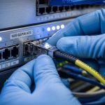
Verify optical reach with measured loss, not just “rated distance”
For MMF SR, do not rely solely on vendor reach claims; measure end-to-end loss including patch cords, couplers, and connector cleanliness. For example, a 10GBASE-SR link that “should” work at 300 m can fail if your patch cords are older, improperly cleaned, or have elevated insertion loss. For SMF LR, validate fiber attenuation and patch loss, and confirm the correct fiber strand mapping. [Source: ANSI/TIA-568 (fiber cabling performance concepts)]

Selection criteria and decision checklist for engineers
When procurement and operations collide, the fastest way to avoid outages is to select by a checklist that maps to the failure modes you actually see in the field. Use this ordered list for each Nokia Enterprise SFP request tied to OmniSwitch AOS.
- Distance and fiber type: confirm MMF OM1/OM2/OM3/OM4 or SMF, then match SR vs LR vs ER behavior.
- Data rate and port profile: confirm SFP vs SFP+ expectations on the OmniSwitch AOS interface.
- Connector and polarity: LC connector type and strand mapping (Tx/Rx) must match your patch plan.
- DOM support and threshold behavior: ensure the module provides standard digital DOM and does not trigger AOS sanity checks.
- DOM accuracy and “out-of-range” risk: if your environment runs hot, verify temperature range and airflow assumptions.
- Operating temperature and airflow: confirm the transceiver grade matches your rack inlet temperature and cooling strategy.
- Switch compatibility and vendor lock-in risk: prefer Nokia Enterprise SFP SKUs that are explicitly qualified for the OmniSwitch platform and AOS release.
- Spare strategy: keep a matched spare pool (same SKU, same DOM behavior) for fast swap and consistent diagnostics.
Common pitfalls and troubleshooting tips for OmniSwitch AOS optics
Most transceiver issues fall into a few repeatable categories. Below are concrete failure modes with root cause and a corrective action you can execute quickly.
Pitfall 1: Wrong speed class transceiver installed
Root cause: A 10G-capable physical form factor is installed into a port expecting 1G SFP behavior (or vice versa). The switch may accept insertion but fail link negotiation.
Solution: confirm the interface capability in the OmniSwitch AOS configuration and match the transceiver standard (SR/LR and data rate). Re-test link after replacement with the correct SKU.
Pitfall 2: Fiber strand mapping reversed
Root cause: LC duplex polarity is wrong (Tx/Rx swapped). Some links appear to negotiate poorly while DOM readings look normal.
Solution: verify patch panel labeling, then perform a controlled swap of the duplex jumpers at the patch field. Clean connectors before reinsert; end-to-end loss measurements should improve immediately.
Pitfall 3: DOM alarms triggered by temperature or EEPROM mismatch
Root cause: the module’s EEPROM identity or DOM scaling does not match what the OmniSwitch expects, or the rack inlet is above module tolerance.
Solution: check AOS logs for DOM-specific alarms, measure rack inlet temperature near the switch, and replace with a Nokia Enterprise SFP SKU that is qualified for the platform. If you must use third-party optics, validate DOM compatibility in a staging bench first.
Pitfall 4: Elevated optical loss from dirty connectors
Root cause: fiber endfaces contaminated by dust after repeated maintenance or during patching.
Solution: follow a cleaning workflow (inspect with fiber scope, clean with lint-free wipes or proper cleaning tools), then re-run optical power checks. This often fixes intermittent errors that look like compatibility failures.
Cost and ROI note for Nokia Enterprise SFP in OmniSwitch environments
Pricing varies by SKU and whether you buy OEM-qualified Nokia Enterprise SFP modules or third-party compatibles. In typical enterprise channels, OEM optics often land in a higher unit cost range (commonly several tens to low hundreds of USD per module depending on reach and data rate), while third-party modules can be cheaper but may carry higher operational risk if AOS DOM/EEPROM validation is strict. From a TCO standpoint, the ROI comes from reduced downtime: a single failed insert can consume hours of engineer time, plus incident risk. If you need consistent diagnostics for operations and audits, standardizing on qualified Nokia Enterprise SFP SKUs for OmniSwitch AOS ports usually wins over time.

FAQ: Nokia Enterprise SFP for OmniSwitch AOS compatibility
Which Nokia Enterprise SFP types are most common for OmniSwitch AOS?
Most deployments use 850 nm SR for short-reach MMF within a few hundred meters, and 1310 nm LR for longer SMF runs. The key is matching the OmniSwitch port’s expected data rate and transceiver profile, not just the wavelength.
How can I tell if the issue is DOM compatibility versus fiber loss?
Check AOS event logs right after insertion. If the switch flags unsupported transceiver or DOM alarms immediately, start with EEPROM/DOM compatibility. If it accepts the module but link remains down or flaps, focus on optical loss, polarity, and connector cleanliness.
Do DOM readings need to be perfectly accurate for AOS to accept the module?
They do not have to be lab-grade identical, but they must be consistent enough to pass AOS sanity checks. Temperature and bias current trends outside expected ranges can trigger warnings or prevent stable operation.
Can I mix OEM Nokia Enterprise SFP and third-party optics in the same OmniSwitch chassis?
It is possible, but operational consistency is not guaranteed. If the platform is strict, third-party EEPROM/DOM behavior can cause intermittent acceptance or alarm states. For critical links, standardize on a single qualified SKU family.
What cable plant measurements matter most for SFP SR links?
End-to-end insertion loss, connector loss, and polarity are the main drivers. Also validate that you are using the correct fiber grade (OM3/OM4 for 10GBASE-SR) and that patch cord quality is consistent across the path.
Where do I find authoritative compatibility guidance?
Start with Nokia Enterprise transceiver datasheets and the OmniSwitch AOS documentation for supported optics. When available, use vendor compatibility matrices tied to your exact switch model and AOS release. [Source: vendor datasheets and platform documentation from Nokia Enterprise and switch OEM documentation]
For reliable OmniSwitch AOS operation, treat Nokia Enterprise SFP selection as a three-layer validation: port profile, optical budget, and DOM/EEPROM acceptance. If you are standardizing a fleet, build a small staging test plan and keep matched spare SKUs for fast recovery.
Next step: Review your rack-level cooling and airflow assumptions, then align optics choices to measured inlet temperatures and link budgets using Data center rack cooling and transceiver temperature management.
Author bio: I have deployed and troubleshot enterprise fiber and transceiver fleets in leaf-spine and access networks, with hands-on work on OmniSwitch-style optics validation, DOM telemetry, and incident response. I focus on practical rack planning, power budgeting, and failure-mode driven compatibility testing to minimize downtime.