In modern business networks, “fiber is fiber” is the kind of sentence that makes field engineers reach for the multimeter and a fresh coffee. This article explains how multi-core and single-core fiber behave differently in day-to-day operations, from switch compatibility to troubleshooting when link budgets get spicy. It helps network owners, architects, and support teams choose the right fiber strategy without betting the uptime budget on vibes.

What “multi-core” changes in real networks
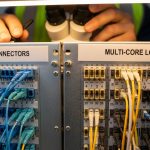
Single-core fiber carries light in one spatial path, while multi-core fiber uses multiple cores within the same cladding, allowing parallel channels. In practice, multi-core can reduce trench space and simplify cabling density, but it also introduces more ways for light to misbehave: crosstalk, coupling variation, and alignment sensitivity. Standards like IEEE 802.3 define how Ethernet optics behave electrically and optically, but the physical fiber type can still dictate whether your optical budget survives deployment reality. If you are planning 10G/25G/100G links, the optics and fiber design must match the intended channelization method rather than assuming “same connector, same fate.”
Optical behavior: crosstalk and coupling
Multi-core systems can suffer from inter-core crosstalk, where power leaks between cores, degrading signal quality (lower OSNR margin). Coupling can vary with temperature, bend radius, and mechanical stress, which matters when racks get warm or someone “helpfully” routes cables against the bend radius recommendations in the datasheet. Single-core fiber is generally more predictable in these respects, especially with mature multimode and singlemode ecosystems.
Pro Tip: If you deploy multi-core to gain density, treat bend radius and connector cleanliness as first-class citizens. Many “mysterious” link flaps are actually inter-core coupling changes triggered by microbends during installation or later cable management.
Key specs comparison: single-core vs multi-core
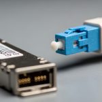
Before you compare reach numbers, remember that “reach” depends on the optics (transceiver type), fiber attenuation, modal behavior, and the link budget. Use the table below as a decision anchor; then verify exact product compatibility with your vendor transceiver datasheets (for example, Cisco SFP-10G-SR style optics for multimode, or Finisar/Fiberstore equivalents for singlemode). Also confirm whether your multi-core fiber is designed for the same signaling format your optics expect (parallel lanes, spatial multiplexing, or a specific core mapping).
| Spec | Single-core fiber | Multi-core fiber |
|---|---|---|
| Core count | 1 core | Multiple cores (varies by design) |
| Typical use | Standard Ethernet optics (SR/LR/ER style) | High-density cabling where spatial parallelism is used |
| Main risk | Attenuation, connector contamination, bends | Inter-core crosstalk, coupling variation, alignment sensitivity |
| Connector ecosystem | Widely standardized; high availability | May require multi-core-aware connectors and polished interfaces |
| Optical budgeting inputs | Attenuation + connector loss + dispersion | Attenuation + connector loss + crosstalk penalties |
| Temperature sensitivity | Generally manageable with standard practices | Can be more sensitive due to coupling changes |
| Operating temperature | Depends on transceiver; common optics are rated roughly -5 to 70 C | Also depends on transceiver; fiber mechanical stress limits still apply |
For reference, IEEE 802.3 Ethernet optics requirements are defined at the interface level, while transceiver vendors specify power levels, receiver sensitivity, and allowable link penalties in their datasheets. For fiber handling requirements, consult ANSI/TIA cabling guidelines such as bend radius recommendations and optical cleaning practices. External references: IEEE 802.3 and ANSI/TIA standards portal.

Deployment scenario: a leaf-spine rollout with tighter pathways
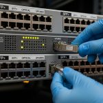
Picture a 3-tier data center leaf-spine topology with 48-port 10G ToR switches feeding 6-spine switches, plus an upgrade path to 25G. The facility has limited overhead cable trays, so the cabling team proposes multi-core to squeeze more parallel links into the same pathway. In the first phase, you light up 40GbE or 100GbE using appropriate optics, verifying each link with an OTDR/OLTS workflow and checking that your multi-core fiber design supports the intended spatial mapping. After go-live, you monitor optics telemetry and error counters, and you enforce a strict bend radius policy during later moves/adds/changes to avoid crosstalk-induced BER drift.
In contrast, a single-core approach might cost more rack space but tends to offer fewer surprises because the connector and fiber behavior are more standardized across mainstream optics. Both approaches can be valid, but the multi-core path demands stronger installation discipline and more validation up front.
Selection checklist engineers actually use
Use this ordered list when deciding between single-core and multi-core fiber for business operations. The goal is to avoid “it works on the test bench” and then faceplant in the ceiling tray.
- Distance and link budget: Confirm attenuation, connector loss, and any additional penalties for crosstalk. Match to your transceiver reach class.
- Switch and transceiver compatibility: Verify DOM support and vendor-qualified optics for your platform. Example optics families include Cisco SFP-10G-SR and common 10G SR modules like FS.com SFP-10GSR-85, but always check the exact transceiver-to-fiber mapping.
- Fiber termination and connector type: Ensure multi-core connectors are compatible with your fiber layout and polishing specs. A “looks similar” connector can still perform terribly.
- DOM and monitoring requirements: If you need real-time power and temperature telemetry, ensure your optics support digital diagnostics (DOM/QSFP-DD equivalents, depending on your gear).
- Operating temperature and mechanical constraints: Validate that expected thermal swings and cable routing will not push stress beyond fiber handling limits.
- Vendor lock-in risk: Multi-core ecosystems may be more proprietary. Ask for documentation on crosstalk performance and recommended OTDR/OLTS test methods.
- Installation validation plan: Define acceptance testing: OLTS for insertion loss and OTDR traces for reflectance and discontinuities.

Common pitfalls and troubleshooting tips
Here are failure modes that show up in the real world, not just in hypothetical lab diagrams.
- Pitfall: Link flaps after cable management changes
Root cause: Microbends or stress change coupling in multi-core fiber, increasing inter-core crosstalk.
Solution: Re-check bend radius compliance, re-terminate suspect sections, and inspect routing for tight turns and kinks. Re-run OLTS and compare against baseline. - Pitfall: “Receiver sensitivity looks fine” but traffic still errors
Root cause: Crosstalk penalties or spatial mapping mismatch can degrade OSNR without obvious power-level failure.
Solution: Validate optics configuration, confirm that the transceiver expects the same channelization method, and test with vendor-recommended reference fibers if available. - Pitfall: High insertion loss right after termination
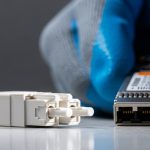
Root cause: Connector contamination or improper polishing on fiber end-faces, especially noticeable with multi-core geometry.
Solution: Use certified cleaning tools, inspect with an end-face scope, and redo termination if end-face defects are visible. - Pitfall: OTDR traces are confusing during acceptance testing
Root cause: Multi-core trace interpretation differs from single-core expectations, and test setup assumptions may be wrong.
Solution: Use the test procedure specified by the fiber manufacturer or transceiver vendor, and document test parameters for repeatability.
Cost and ROI note: the price of density vs the price of peace
In typical enterprise buying, third-party single-core fiber and optics often come at a lower initial cost, while multi-core deployments can carry higher up-front engineering and termination costs due to specialized connectors and validation. As a rough market reality check, many 10G SR optics and single-core cabling components may land in the tens to low hundreds of dollars per link component, while multi-core solutions can be higher depending on transceiver type and termination labor. TCO should include labor for acceptance testing, likelihood of rework, and downtime risk. If your cabling pathways are truly constrained and you can enforce strict installation QA, multi-core can improve utilization; otherwise, single-core often wins on operational simplicity.
FAQ
Is multi-core fiber always faster than single-core?
No. Multi-core can enable higher parallel capacity through spatial multiplexing, but the realized throughput depends on the transceivers, mapping, and link budget. If your optics only support a single spatial channel, you will not magically get extra bandwidth.
Will my existing switches work with multi-core?
Switches typically rely on compatible optics, not the fiber label alone. You must confirm transceiver qualification, DOM behavior, and whether the optics expect multi-core channelization. Start by checking vendor-qualified transceivers for your exact switch model.
What test equipment should we use for acceptance?
At minimum, use OLTS for insertion loss and OTDR for fault localization, following the procedures recommended by the fiber and transceiver vendors. For multi-core, ensure the test interpretation method matches the fiber design so you do not “pass” a problem you cannot see.
Why do multi-core links sometimes degrade over time?
Mechanical stress and microbends can change coupling and increase inter-core crosstalk, especially after moves, adds, and changes. Temperature swings can also contribute, so monitor error counters and optic diagnostics over time.
Can I mix single-core and multi-core in the same tray?
Yes, physically you can route them together, but do not mix connector types or assumptions. Keep labeling strict, and segregate fiber groups by link mapping to avoid cross-termination mistakes.
Where should we start if we are unsure?
Run a pilot: light up a small number of links end-to-end, validate with OLTS/OTDR, and observe telemetry for at least a few weeks. If performance is stable and installation discipline is feasible, scale carefully.
If you want fewer surprises, treat fiber type as a system design variable, not a procurement afterthought. Next step: compare optics families and choose transceivers that match your fiber strategy via multi-core transceiver compatibility.
Author: A UI/UX-leaning network designer who has watched too many cable trays become accidental science experiments. I translate field constraints into clean decisions, so your links stay up and your weekends stay yours.