In many office and campus networks, the fiber choice looks simple until outages, distance limits, or upgrade deadlines hit. This guide helps operations, field engineers, and procurement teams decide whether multi-core or single-core fiber better fits their business constraints. You will get practical selection criteria, real deployment math, and troubleshooting patterns grounded in how optics actually behave in the field.
Single-core vs multi-core: what changes in real operations
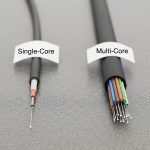
Single-core fiber carries one optical path per strand. Multi-core fiber packs multiple cores into one cladding, aiming to increase capacity without adding more physical fiber bundles. In practice, multi-core is sensitive to core-to-core coupling, connectorization quality, and splicing alignment, so the “capacity per trench meter” story only holds if your installation discipline matches the hardware.
For business operations, the decision often becomes a workflow question: do you have standardized splicing/termination practices, trained technicians, and a maintenance plan for connector and patch panel churn? If the answer is “mostly yes,” multi-core can reduce duct occupancy and speed early deployments. If it is “we patch ad hoc,” single-core remains the safer operational baseline.
Key technical differences that matter to buyers
- Core count and coupling: multi-core fibers introduce inter-core crosstalk that must be budgeted like link loss and OSNR margin.
- Termination quality: connector and polarity control are more forgiving on single-core than on multi-core, where misalignment can degrade multiple cores at once.
- Splice repeatability: multi-core splicing requires tight alignment tooling and process control to avoid uneven per-core attenuation.
- Equipment ecosystem: not every switch, transceiver, or test workflow supports multi-core link validation end-to-end.
Standards and test approaches still anchor the conversation. Link design typically references optical performance concepts from IEEE 802.3 optics link budgets, while cabling and field testing practices align with structured cabling guidance such as IEEE 802.3 and cabling test expectations from ANSI/TIA cabling standards.
Specs that decide: wavelength, reach, power, and connector reality
Engineers rarely choose fiber by the name alone. They choose by measured parameters: insertion loss after termination, per-core attenuation, and end-to-end crosstalk. Below is a practical comparison using common business optics patterns at 850 nm (short reach) and 1310/1550 nm (long reach), assuming typical transceiver classes.

| Spec | Single-core fiber (typical) | Multi-core fiber (typical) |
|---|---|---|
| Core arrangement | One core per strand | Multiple cores in one cladding |
| Common wavelengths | 850 nm, 1310 nm, 1550 nm | 850 nm and/or 1310/1550 nm depending on transceiver support |
| Reach (example classes) | Short reach: tens to ~300 m at 850 nm; longer: km-class at 1310/1550 nm | Reach depends on per-core crosstalk budget; often best for structured links with controlled installation |
| Link impairment to budget | Attenuation + connector/splice loss | Attenuation + connector/splice loss + core-to-core crosstalk |
| Connectorization | LC/SC with standard polarity control | Adapter and connector must preserve core alignment; polarity and mapping become more critical |
| Power and safety | Laser safety practices per transceiver class; normal eye/skin precautions | Same laser safety practices, but troubleshooting can involve more per-core measurements |
| Operating temperature | Transceivers typically support extended ranges (check datasheet; often around 0 to 70 C) | Same for transceivers; fiber temperature effects are typically secondary to installation quality |
For transceivers, vendor datasheets matter as much as fiber type. For example, common enterprise optics include Cisco SFP-10G-SR for 10G short reach and multi-vendor equivalents like Finisar FTLX8571D3BCL and FS.com SFP-10GSR-85 (part numbers vary by revision and temperature grade). Always confirm that the transceiver supports the wavelength and that your test plan validates the specific fiber behavior you plan to deploy.
Deployment story: when multi-core saves trench space and time
In a 3-tier data center leaf-spine topology with 48-port 10G ToR switches, a facility team often runs fiber from ToR to aggregation at distances of 80 to 120 m, then adds patching for growth. Suppose the building duct is already at capacity: you need to add 16 additional 10G links between two rows of racks within a month, with minimal downtime. If the site can reuse an existing trunk route but lacks room for new single-core bundles, multi-core can reduce cable count by carrying multiple cores per strand, keeping pathway occupancy stable.
In one field workflow, a contractor used multi-core cabling with pre-terminated trunks and strict core mapping labels. The team validated links using per-core loss checks at commissioning and then rechecked after rack moves. The operational win was faster rerouting: instead of pulling new single-core bundles through tight trays, they reterminated patch ends while preserving the backbone. The operational risk was higher if connectorization quality slipped, so the team assigned a single certified splicer crew for the whole run.

Selection checklist: how engineers choose multi-core without regret
Use this ordered checklist during design review. It is written for the moments when procurement asks “can we just buy it” and field teams ask “will it test cleanly.”
- Distance and margin: confirm attenuation targets and expected insertion loss after termination; validate that your link budget has room for worst-case connectors/splices.
- Transceiver and switch compatibility: verify the optics module family and wavelength class are explicitly supported for your deployment type; do not assume multi-core works with any “standard” transceiver.
- DOM and monitoring support: ensure your transceivers provide DOM (digital optical monitoring) where needed for ops visibility; plan monitoring thresholds for early degradation.
- Connector and adapter ecosystem: confirm the exact adapter types and polarity/core mapping method; request connector factory test reports if available.
- Operating temperature and environment: check transceiver temperature range and ensure cabling pathway conditions match manufacturer limits.
- Vendor lock-in risk: assess whether replacement transceivers and spares require a specific vendor or proprietary mapping workflow; prefer solutions with published test procedures.
- Test plan maturity: define commissioning and acceptance tests that can validate per-core behavior for multi-core, not only end-to-end “it lights” checks.
Pro Tip: In multi-core deployments, “pass the continuity test” is not enough. Field teams often discover that per-core loss variation only shows up after patch panel rework, so schedule a second validation after the first round of rack moves and label verification.
Common pitfalls and troubleshooting tips
Most failures are not mysterious; they are repeatable process gaps. Here are concrete failure modes and how to respond quickly.
-
Pitfall 1: Crosstalk surprises after installation
Root cause: uneven core alignment from connectors or splices increases core-to-core coupling.
Solution: require per-core characterization during acceptance; re-terminate or re-splice the affected section using the same connector and splice process used for the rest of the run. -
Pitfall 2: “Works on one port, fails on another”
Root cause: core mapping or polarity labeling mismatch between trunk side and patch panel side.
Solution: perform a structured mapping audit: label verification, trace the exact patch cord pairing, and update documentation before further troubleshooting. -
Pitfall 3: Intermittent link flaps under thermal cycling
Root cause: marginal connector ferrule condition, strain in slack loops, or a too-tight bend radius in a pathway.
Solution: inspect bend radius compliance, relieve strain, clean connectors, and retest with the same transceiver model after rework. -
Pitfall 4: Overlooking transceiver temperature grade
Root cause: deploying transceivers outside specified operating temperature, leading to higher error rates.
Solution: confirm datasheet temperature range and environmental controls; swap to a compatible temperature grade if needed.

Cost and ROI: where multi-core pencils out
Pricing varies by region and connectorization approach, but the economics usually come from three buckets: backbone cable cost, installation labor, and pathway capacity savings. In many businesses, multi-core wins when trench or tray capacity is the limiting factor and when you can standardize termination and testing labor.
Typical TCO logic: if multi-core reduces the number of backbone pulls and accelerates expansion by weeks, labor savings and reduced downtime can outweigh any premium for specialized termination and per-core testing. If your team frequently reconfigures patching without strict mapping discipline, the rework cost can erase the initial savings. Treat multi-core as an “installation quality dependent” asset: the ROI improves when you can enforce process control.
FAQ
Is multi-core fiber always higher capacity than single-core?
Not automatically. Multi-core can increase capacity per strand, but only if your optics and test plan manage crosstalk and per-core alignment. If your environment requires frequent rework, single-core may deliver higher reliable throughput per dollar.
Can I use standard transceivers with multi-core fiber?
Sometimes, but you must confirm explicit support for the wavelength and link type. Always validate with the specific transceiver part number and manufacturer documentation, and run commissioning tests that match the multi-core behavior you installed.
What tests should we run at acceptance?
For single-core, end-to-end loss and continuity are typical. For multi-core, add per-core validation and core mapping checks, and consider characterization that can reveal core-to-core crosstalk issues before the network goes live.
Does multi-core reduce downtime during expansions?
Often yes when pathway capacity is constrained and when you can reuse existing trunks. However, expansions can increase risk if patch panel remapping is sloppy, so enforce labeling and run a second validation after first rack moves.
What is the biggest operational risk of choosing multi-core?
Operational risk usually comes from inconsistent termination/splice quality and mapping errors. The mitigation is process control: certified crews, standardized adapters, and a test plan that goes beyond “it lights.”
How should procurement think about vendor lock-in?
Ask whether replacements require proprietary core mapping tools or specific connector systems. Favor vendors that publish clear testing procedures and provide spares with compatible optics and operational monitoring support.
If you are deciding between single-core and multi-core, treat the choice as a system design: fiber behavior, transceiver support, and field testing discipline. Next, review fiber-optic-transceiver-selection-checklist to align optics, budget, and operational monitoring before ordering spares.
Author bio: I have deployed and troubleshot enterprise fiber links using OTDR, optical power meters, and transceiver DOM workflows in real server room migrations. I focus on measurable link budgets, connectorization quality, and operational test plans that prevent repeat outages.