When a fiber uplink bundle starts flapping or load balancing looks uneven, the root cause is often not LACP itself, but the transceiver and optics behavior across the aggregated ports. This article helps network engineers and field operators implement LAG fiber optic links with LACP using enterprise SFP/SFP+/QSFP optics while minimizing incompatibilities, optical power issues, and hashing surprises. You will get a step-by-step deployment workflow, a practical spec comparison, and troubleshooting steps grounded in what we see in production.
Prerequisites: what you must verify before cabling
Before you touch optics, confirm that your switches support LACP across the exact interface types you plan to aggregate. Most platforms allow only like-for-like speeds and modes in a single LAG, and some require the same transceiver vendor or at least the same DOM reporting format. Also confirm that your hashing algorithm is compatible with your traffic patterns, especially if you run east-west replication or storage traffic.
Inventory and standards alignment
- Switch capability: Verify LACP support and that the member ports are eligible for LAG at the target speed (for example, 10G, 25G, 40G).
- Ethernet standard: LACP is defined in IEEE 802.1AX (link aggregation control protocol) and builds on IEEE 802.3 Ethernet PHY behavior. Use that baseline when interpreting counters and partner negotiation.
- Optics interface: Ensure the optics are supported by the switch (vendor compatibility lists matter for strict DOM and EEPROM parsing).
- Fiber plant: Confirm fiber type and loss budget with an OTDR or at least measured insertion loss; do not rely on fiber labels alone.
Expected outcome
You can confidently state: “This switch model supports LACP on these port types at this speed, and the optical budget is adequate for the measured fiber loss.” That removes the two most common causes of LAG instability: member incompatibility and optical brownouts.

Step-by-step implementation: build a resilient LAG fiber optic with LACP
Use a controlled rollout so you can attribute any change to a specific variable: transceiver selection, cabling polarity, or LACP parameters. The goal is to make every member port behave similarly at the PHY and optics layers so the LAG has stable synchronization and predictable hashing.
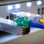
Select optics that match the PHY and budget
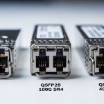
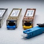
Choose transceivers that match the exact link type: SR for multimode, LR for single-mode, or ER for longer reach. Example optics commonly used in 10G enterprise deployments include Cisco SFP-10G-SR and compatible third-party modules such as Finisar FTLX8571D3BCL (10GBASE-SR) or FS.com SFP-10GSR-85 (10GBASE-SR). For 25G and 40G, follow the same SR/LR/ER logic and ensure the switch supports that form factor and speed.
Operationally, pick modules with stable transmit power and consistent receiver sensitivity. If you must use third-party optics, validate that the switch accepts their DOM fields and that alarms (LOS, TX power low, RX power out of range) do not trigger under load.
Expected outcome: All LAG member ports run the same PHY type and optics class, minimizing member-to-member behavior drift.
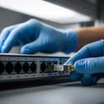
Ensure fiber polarity and connector cleanliness
For duplex fiber, verify which pair is RX and TX at each end. In practice, field teams often discover that one link is “crossed” while the others are “straight,” leading to intermittent link up/down or high BER. Clean connectors before insertion, and if you have budget, inspect with a fiber scope.
Expected outcome: You avoid silent optical degradation that later appears as CRC errors and LAG member churn.
Configure LACP mode and member selection
Configure LAG with LACP in an active or passive mode depending on your peer behavior. Many teams set both sides to active for faster convergence. Also ensure the LAG is created with the correct VLAN handling model (trunk vs access) and that the member ports have consistent VLAN membership.
Expected outcome: Member ports reach synchronization with the LACP partner and remain stable under link load.
Validate LAG hashing expectations
Even when LACP is healthy, operators sometimes interpret imbalanced traffic as a failure. LAG hashing typically uses one or more header fields (often source/destination MAC, IP, or TCP/UDP ports). If your application uses many flows with varied 5-tuples, load spreads well; if it uses a single elephant flow, it will concentrate on one member.
Expected outcome: You can explain utilization distribution and correlate it with expected hashing behavior, not assume “uneven traffic equals broken LAG.”
Monitor optics and link health counters
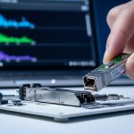
After bringing the LAG up, watch optics telemetry (DOM) and interface counters. Track CRC errors, FCS errors, symbol errors (platform dependent), and LACP state changes (for example, “selected/aggregated” status). If the switch exposes per-lane diagnostics on higher-speed optics, watch for warning thresholds.
Expected outcome: You confirm that link quality is stable and that no member is continuously transitioning due to optical alarms.

Key optics specs and reach: what matters for LAG fiber optic stability
In a LAG, optics differences can create subtle member-level issues: slightly different transmit power, receiver sensitivity drift over temperature, or DOM parsing quirks that trigger alarms. While LACP aggregates at layer 2, the PHY and optics still determine whether each member remains “good enough” to participate.
Comparison table: common 10G SR optics used in LAGs
Below is a representative comparison for 10GBASE-SR style modules. Exact values vary by vendor and revision, so treat this as an engineering checklist rather than a promise.
| Module class | Wavelength | Nominal reach | Connector | DOM/diagnostics | Operating temp | Typical use in LAG |
|---|---|---|---|---|---|---|
| 10GBASE-SR (850 nm) | 850 nm | Up to 300 m on OM3 (typical) | LC duplex | Usually supported | Often 0 to 70 C (varies) | Short-reach datacenter uplinks |
| Cisco SFP-10G-SR | 850 nm | OM3/OM4 dependent | LC duplex | Vendor DOM fields | Vendor specified | Strict compatibility environments |
| Finisar FTLX8571D3BCL (example 10G SR) | 850 nm | OM3/OM4 dependent | LC duplex | DOM supported on most platforms | Vendor specified | Cost-optimized SR deployments |
| FS.com SFP-10GSR-85 (example 10G SR) | 850 nm | OM3/OM4 dependent | LC duplex | DOM supported on many platforms | Vendor specified | Third-party optics in controlled plants |
What to measure beyond the datasheet
- Transceiver power levels: Compare TX power and RX power across members. If one member runs near thresholds, it may drop under temperature swings.
- Link error rate: CRC/FCS increments indicate optical or cabling issues even when the link is “up.”
- Temperature and airflow: In dense racks, optics can see higher temperatures than expected, especially with blocked vents.
- Connector grade and cleanliness: Dirty LC endfaces create repeatable intermittent failures that look like LACP flaps.
Pro Tip: In the field, the most reliable LAG fiber optic rollouts standardize optics across all member ports and validate DOM alarm thresholds under peak traffic. If you mix “functionally compatible” optics, you may still see stable links—until temperature and aging push one module into a warning state, causing member reselection and brief traffic loss that operators misattribute to LACP.
Selection criteria: how engineers choose LAG fiber optic components
Use a checklist that reflects real operational risks: compatibility, optical margin, and the likelihood of future replacements behaving the same way.
- Distance and fiber type: Match SR/LR/ER to OM3/OM4 or single-mode fiber, then verify loss with measured insertion loss or OTDR.
- Switch compatibility: Confirm the transceiver form factor and speed are supported and that DOM fields are accepted without warnings or refusals. Prefer vendor-approved lists when uptime is critical.
- DOM support and thresholds: Ensure the switch can read DOM and that alarm thresholds are consistent across modules.
- Operating temperature: Validate module temperature range against rack ambient and airflow; consider airflow modeling for high-density ToR and leaf-spine stacks.
- Budget and procurement model: OEM optics can be higher cost; third-party can reduce spend but increases compatibility and warranty variability.
- Vendor lock-in risk: If you must use a specific vendor for strict DOM compatibility, plan spares so replacements remain consistent.
- Future upgrade path: If you plan to migrate from 10G to 25G or 40G, standardize fiber infrastructure and consider whether the current cabling supports the future reach class.
Real-world deployment scenario: leaf-spine uplinks with predictable hashing
In a 3-tier data center leaf-spine topology, a team deployed 4-member LAG fiber optic uplinks between each top-of-rack switch and a spine switch pair. Each leaf had 48x 10G ToR access ports and 8x 10G uplinks, aggregated as 2 LAGs of 4 members to separate traffic classes. They used 10GBASE-SR optics on OM4 links with measured insertion loss around 1.0 dB per direction after patch panel cleaning, leaving margin for aging and reconnection cycles. After enabling LACP active-active, they monitored per-port CRC error counters and confirmed that all members stayed below 10 CRC errors per hour during peak replication windows; traffic distribution matched the expected hashing behavior for their mix of TCP flows.

Common mistakes and troubleshooting tips
Even experienced teams make repeatable mistakes. Below are three high-frequency failure modes with root causes and practical fixes.
Failure mode 1: LAG members keep dropping due to optical thresholds
Root cause: One transceiver runs hotter or has lower TX power, pushing RX below the receiver threshold during peak load or after a rack airflow change.
Solution: Compare DOM telemetry across members (TX/RX power, temperature, bias current if available). Replace the lowest-margin module first and ensure consistent airflow. If using third-party optics, test them in the same rack before broad rollout.
Failure mode 2: High CRC/FCS errors on only one member, causing reselection
Root cause: Dirty connectors, damaged fibers, or a single polarity/cabling mismatch that creates marginal optical alignment.
Solution: Clean and re-terminate LC ends, inspect with a fiber scope, and verify RX/TX mapping end-to-end. Confirm that the patching method is consistent with the other members.
Failure mode 3: “Uneven traffic” mistaken for a broken LAG
Root cause: Hashing algorithm concentrates flows because your traffic uses a limited set of header fields (for example, many packets from one source/destination pair).
Solution: Measure member utilization and correlate with flow logs. If needed, adjust hashing settings (if supported) or change application behavior to increase flow diversity. Ensure you are not also applying asymmetric routing that changes the LAG hashing inputs.
Cost and ROI note: balancing OEM optics, third-party modules, and downtime risk
In many enterprise environments, OEM optics can cost materially more than third-party equivalents. As a rule of thumb, a 10G SR transceiver might land in the tens of dollars to over a hundred dollars range depending on vendor and channel, while third-party modules often undercut that price. The ROI question is not only purchase cost: the total cost includes spares strategy, warranty handling, and the operational time spent diagnosing DOM alarms and intermittent fiber issues.
For mission-critical uplinks, teams often standardize on OEM for the first deployment wave, then expand to third-party only after compatibility validation and a controlled burn-in period. This reduces the chance that a “cheap” optics swap becomes an outage driver.
FAQ
How do I know my LAG fiber optic ports are truly compatible?
Verify at two layers: switch eligibility for LAG member ports at the target speed and optics compatibility in the switch vendor documentation. Then confirm in operation that all member interfaces show consistent PHY negotiation and stable DOM readings without recurring alarms.
Can I mix different transceiver vendors in the same LAG?
Sometimes it works, but it increases risk. The safest approach is to use the same module class and ideally the same vendor and revision across all members; if you must mix, validate DOM alarms and error counters under peak load.
What fiber reach should I budget for LAG uplinks?
Budget for measured insertion loss plus margin for patch panel changes and aging. Use your OTDR or measured loss to ensure you stay comfortably below receiver sensitivity limits, not just within “datasheet reach.”
Why does my LACP LAG show member churn during temperature spikes?
Optics can drift with temperature, especially if airflow is restricted. Check DOM temperature and optical power warnings, then improve airflow or replace the lowest-margin module.
How should I validate load balancing across LAG members?
Confirm hashing inputs for your platform and compare member utilization to flow patterns. If you see one member saturated, it may be expected for elephant flows; use traffic engineering or adjust application flow diversity if needed.
What is the fastest way to troubleshoot a suspected optics problem?
Start with the link that has errors or flaps. Swap optics between a stable member and the suspect port, re-check DOM alarms, then clean and verify fiber polarity. If the issue follows the module, replace it; if it stays on the cable path, focus on cleaning and fiber integrity.
If you want the next step after optics selection, review your LAG configuration model and VLAN handling to ensure consistent behavior during failover: LACP configuration and VLAN design for aggregated links.
Author bio: I design and operate high-availability switching systems and have deployed LACP-based uplink fabrics in constrained datacenter environments. My work focuses on transceiver-level validation, optical power margining, and resilient change control to prevent link churn.