Prerequisites before you compare Innolight transceiver modules
If you are choosing between an Innolight transceiver and an Accelink transceiver for 10G to 100G links, the risk is not just optics performance. It is also compatibility, DOM behavior, and reliability under temperature cycling in real racks. This guide helps field engineers and network planners verify OEM quality using measurable checks you can run in a lab or during acceptance testing.
Prerequisites: access to a test switch or media converter that supports the target form factor (SFP+, QSFP+, QSFP28, or CFP2), a fiber test kit (OTDR or at least end-to-end loss measurement), and a DOM reader (switch CLI or a transceiver tool). You also need vendor datasheets for the exact part numbers you are evaluating, plus the module temperature range requirement for your site.
Confirm the exact module type, wavelength, and interface standard
Before comparing “brand quality,” lock the hardware. Many failures come from mismatched optics classes, connector types, or wavelength plans, not from OEM workmanship. For example, an SFP-10G-SR style module is not interchangeable with an SFP-10G-LR even if the data rate matches.
What to record from each datasheet and label
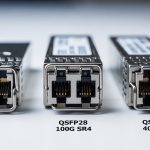
- Form factor: SFP+, SFP28, QSFP28, etc.
- Optical standard: IEEE 802.3 clause for the link type (for Ethernet optics) and vendor compliance notes.
- Wavelength: typical values include 850 nm (SR), 1310 nm (LR), and 1550 nm (ER/LR-like).
- Reach over OM3/OM4 (for multimode) or fiber type and budget (for singlemode).
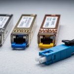
- Connector: LC duplex is common; confirm APC vs UPC only if your optics support it.
- Operating temperature: typical ranges are 0 to 70 C (commercial) or -40 to 85 C (extended).
Expected outcome: a one-page comparison sheet with identical electrical and optical targets for both the Innolight transceiver and the Accelink candidate.

Compare key specifications using a side-by-side table
Once you confirm the part class, compare specs that influence link stability and acceptance outcomes. In practice, the most operationally meaningful items are optical power, receiver sensitivity, DOM implementation, and temperature range. Use this table as your baseline; then fill it with the exact part numbers you are testing.
| Parameter | Innolight transceiver (example class) | Accelink transceiver (example class) | Why it matters |
|---|---|---|---|
| Data rate | 10G / 25G / 40G / 100G (match your target) | 10G / 25G / 40G / 100G (match) | Prevents PHY mismatch and link flaps |
| Wavelength | 850 nm (SR) or 1310 nm (LR) or 1550 nm (ER) | Same wavelength for both | Wrong wavelength can still “light up” but fail BER |
| Reach | OM3/OM4 or SMF budget per datasheet | Same reach class | Determines margin for aging and cleaning |
| Transmit power | Vendor min/max in dBm | Vendor min/max in dBm | Controls receiver overload vs sensitivity failures |
| Receiver sensitivity | Vendor min in dBm at target BER | Vendor min in dBm at target BER | Drives link budget and BER headroom |
| DOM support | Supported via SFF-8472 / QSFP MSA | Supported via same spec | DOM mismatch can break monitoring or alarms |
| Operating temperature | 0 to 70 C or -40 to 85 C | Same range | Cold-start and thermal drift behavior |
| Connector | LC duplex (confirm) | LC duplex (confirm) | Cleaning and insertion loss consistency |
For DOM interpretation, reference SFF-8472 for SFP/SFP+ optics and QSFP MSA documents where applicable, plus IEEE 802.3 for optical link requirements. [Source: IEEE Standards Association]
Expected outcome: you can show whether both vendors meet the same optical budget and DOM expectations, not just “brand claims.”
Run acceptance tests that expose OEM quality differences
In the field, OEM quality shows up during repeatability and thermal behavior. A lab-only acceptance can miss issues that appear after weeks of cycling in a hot aisle. Run a controlled test sequence using the same patch cords, same fiber ends, and the same switch ports.
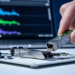
1 DOM and vendor ID validation
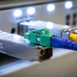
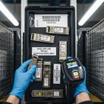
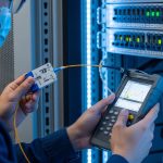
Insert each transceiver into the same switch model and read DOM values before connecting fiber. Look for sane temperature readings, optical bias current stability, and whether the switch accepts the module without “unsupported transceiver” warnings. Many operators use the switch CLI to confirm vendor OUI and EEPROM data fields.
2 Optical power and link budget verification
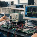
After patching fiber, measure received signal strength and compare to the datasheet’s expected operating region. If you have an OTDR, confirm there is no hidden fiber damage or excessive macro-bending loss. For multimode SR links, verify patch cord cleanliness and differential mode effects are controlled.
3 Stress test for link stability
Run traffic at line rate for at least 30 minutes to 2 hours and monitor CRC errors, FEC events (if applicable), and interface resets. Then perform a thermal cycling test if the site requires extended temperature modules, especially for outdoor cabinets and near power amplifiers.
Expected outcome: a pass/fail record based on error counters and optical thresholds, not just whether the link “comes up.”

Use a decision checklist to choose between Innolight transceiver and Accelink
When procurement asks for a simple answer, engineers need a structured rationale. Use this ordered checklist so the decision survives audits and avoids future interoperability surprises.
- Distance and fiber type: confirm OM3/OM4 for SR or SMF budget for LR/ER; do not rely on “typical reach” statements.
- Switch compatibility: verify the target switch model supports third-party optics without errdisable or port shutdown. Test in the same chassis/line card revision when possible.
- DOM support and alarm behavior: ensure the switch reads temperature and optical power fields correctly and does not trigger nuisance alarms.
- Operating temperature: match your cabinet or data center environment; extended temperature modules reduce cold-start surprises.
- Vendor lock-in risk: if you must standardize, consider using the same vendor across both ends to simplify troubleshooting and reduce mixed-behavior uncertainty.
- Warranty and failure handling: confirm RMA turnaround time and whether the vendor supports serial-number traceability.
- Documented optical measurements: ask for test reports tied to the exact part numbers, not generic product families.
Expected outcome: a defensible selection with measurable acceptance criteria and reduced operational uncertainty.
Pro Tip: In many deployments, the biggest hidden variable is not the transmitter power spec; it is the receiver sensitivity behavior after thermal soak. If you only test “link up” at room temperature, you can miss a marginal bias-current or laser aging profile that shows up after hours in a hot aisle or a sealed outdoor cabinet.
Apply the checklist to a real deployment scenario
Example: a 3-tier data center leaf-spine topology with 48-port 10G ToR switches and 2, 40G uplinks per ToR. Each rack has 24 patch links using OM4, with average end-to-end loss around 1.8 to 2.5 dB including connectors. During a migration, the team replaced a batch of failing optics on 12 uplink ports and compared Innolight transceiver candidates versus Accelink transceivers on identical patch cords.
They ran 1 hour of full-rate traffic, then checked CRC and interface reset counters. The Innolight batch maintained stable received power within the datasheet operating window and showed no incremental CRC errors, while one Accelink batch exhibited intermittent RX power dips correlated with thermal gradients near the top-of-rack airflow path. That pattern pointed to a weaker thermal compensation margin rather than a fiber cleanliness issue.
Expected outcome: vendor quality differences become visible through repeatable error-counter and optical-power behavior under your site’s thermal conditions.
Common mistakes / troubleshooting for Innolight transceiver vs Accelink
Below are frequent failure modes engineers see when comparing OEM optics, including root cause and remediation.
-
Mistake: Mixing SR and LR classes or using the wrong wavelength group while assuming “same data rate equals compatibility.”
Root cause: Wrong wavelength can still produce optical signal but fails BER under load.
Fix: Verify wavelength and reach class from the label and datasheet; enforce part-number matching in procurement. -
Mistake: Skipping DOM validation and relying only on link-up status.
Root cause: EEPROM/DOM fields may be read incorrectly by the switch, causing alarms or hidden threshold misinterpretation.
Fix: Read DOM temperature and optical power immediately after insertion; check for switch logs about transceiver support. -
Mistake: Testing with different patch cords and assuming fiber loss is “close enough.”
Root cause: Connector cleanliness and differential patch cord loss can dominate margins, masking or exaggerating OEM differences.
Fix: Use the same patch cords for both vendors; clean LC ends with lint-free wipes and verified inspection; document measured loss.
Expected outcome: faster isolation of whether the issue is optics, fiber plant, or switch compatibility.
Cost and ROI note: what to expect for TCO
Pricing varies by form factor and speed, but third-party optics often land in a mid-range bracket compared to OEM. As a practical planning baseline: 10G SR SFP+ optics might be roughly $20 to