If your industrial gateway is flapping between “link up” and “intermittent traffic,” the root cause is often the industrial gateway transceiver rather than the application layer. This article helps network engineers and OT/IT field teams compare common fiber transceiver families (SFP, SFP+, SFP28) for industrial IoT gateways, with practical selection and troubleshooting guidance. You will get measurable spec comparisons, deployment assumptions, and a decision matrix you can use during procurement and commissioning.
SFP vs SFP+ vs SFP28: performance and optics tradeoffs
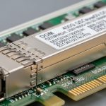
Industrial gateways typically terminate uplink fiber from sensors, PLC concentrators, or edge compute nodes into a managed switch or industrial router. The transceiver family you pick determines data rate, optical budget headroom, and how tolerant the link is to aging optics, connector contamination, and temperature swings. In practice, the “best” choice is the one that meets the link budget with margin, matches the switch’s electrical interface, and stays within the vendor’s specified operating temperature range.
Data rate and lane signaling differences
SFP (commonly 1G) uses 1.25 Gbps line rates (e.g., 1000BASE-SX/LX depending on optics). SFP+ (commonly 10G) runs at 10.3125 Gbps and often supports 10GBASE-SR or 10GBASE-LR. SFP28 (commonly 25G) runs at 25.78125 Gbps and is used for 25GBASE-SR/LR in many modern industrial aggregation designs. Faster optics reduce oversubscription pressure but can increase cost and tighten timing/compatibility constraints.
Wavelength and reach: what matters for plants
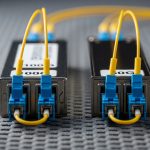
Short-reach (SR) modules typically use 850 nm multimode fiber (MMF) for shorter distances (often 300 m to 400 m class limits depending on link budget and fiber grade). Long-reach (LR) modules typically use 1310 nm over single-mode fiber (SMF) for kilometer-scale distances. For industrial plants with patch panel runs and frequent maintenance, SMF with APC/UPC discipline and good cleaning often reduces operational surprises.

Spec comparison: reach, connectors, DOM, temperature, and power
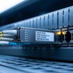
When comparing industrial gateway transceivers, engineers should verify the exact optical standard (e.g., SR vs LR), the expected fiber type, and the vendor’s temperature and optical power ranges. Also check whether the switch/router supports digital optical monitoring (DOM) and whether it enforces vendor-specific authentication. Below is a realistic head-to-head comparison of typical module classes used in industrial gateway uplinks.
| Category | Typical standard | Wavelength | Fiber type | Target reach (typical) | Connector | DOM | Operating temp (typical) | Typical power |
|---|---|---|---|---|---|---|---|---|
| SFP 1G | 1000BASE-SX or LX | 850 nm or 1310 nm | MMF or SMF | ~550 m (SX on good MMF) / up to 10 km (LX) | LC | Often available | -10 to 70 C or extended variants to -40 to 85 C | ~0.8 to 1.5 W |
| SFP+ 10G | 10GBASE-SR or LR | 850 nm or 1310 nm | MMF or SMF | ~300 m (SR) / up to 10 km (LR) | LC | Common | Commercial or extended (-40 to 85 C variants exist) | ~1.5 to 3.5 W |
| SFP28 25G | 25GBASE-SR or LR | 850 nm or 1310 nm | MMF or SMF | ~70 m (SR on typical OM3) to ~300 m (on higher-grade MMF) / up to 10 km (LR) | LC | Common | Often extended in industrial SKUs | ~2.0 to 4.5 W |
For standards context, the physical layer behavior maps to IEEE families such as IEEE 802.3 for Ethernet optics and link characteristics, while DOM behavior is standardized at the module interface level and implemented per vendor. For practical compatibility, always verify your switch or router’s transceiver matrix and DOM expectations. See [Source: IEEE 802.3 Ethernet Working Group] and vendor datasheets for the exact module class you intend to deploy. IEEE 802.3 standards portal
Concrete part examples engineers recognize
Examples of common optics used for industrial gateway uplinks include Cisco-branded or compatible 10G SR modules such as Cisco SFP-10G-SR, and third-party parts like Finisar FTLX8571D3BCL (10GBASE-SR class) or FS.com SFP-10GSR-85 (10GBASE-SR class). For 25G, you will often see SFP28 SR modules in vendor catalogs with OM3/OM4 reach claims that depend heavily on link budget and fiber attenuation. Always treat “reach” as a budgeted claim, not a guarantee, and validate with your plant’s measured fiber loss.
Pro Tip: In industrial sites, the biggest hidden variable is not the transceiver spec sheet; it is connector cleanliness and patch panel loss. A single dirty LC ferrule can add enough insertion loss and back-reflection to push an otherwise “within spec” link into marginal operation, especially at 25G where tolerances shrink.
Cost and ROI: OEM vs third-party transceivers in industrial deployments
Cost decisions are rarely just about unit price. Total cost of ownership (TCO) includes failure rate, lead time, spares inventory depth, time to troubleshoot, and compatibility friction during field swaps. OEM modules can reduce deployment risk when switches enforce strict optics policies, while third-party modules can materially lower procurement spend if they are validated for your platform and environment.
Typical price bands you can budget
In many markets, budgetary ranges for transceiver modules used in industrial gateways look like this (prices vary by vendor, volume, and temperature grade): SFP 1G often lands around tens of dollars; SFP+ 10G commonly ranges from roughly $50 to $200; SFP28 25G often ranges from roughly $120 to $400. Extended-temperature industrial SKUs and SMF LR optics tend to increase cost. If you stock spares, you should also budget for the operational cost of carrying inventory and the risk of obsolescence.
Operational ROI: the “downtime math”
Assume a maintenance window costs $500 to $2,000 in technician time across shift coverage, plus production disruption if the gateway impacts control or monitoring flows. If a compatible third-party module reduces purchase cost by $80 per unit but increases the probability of a field failure from 0.5% to 2% per year, the expected downtime cost can erase the savings quickly. The ROI model should include your actual swap MTTR, your measured failure history, and your switch’s transceiver authentication policy.
Compatibility: the real constraints inside switches and industrial routers
Even if two transceivers both say “10GBASE-SR,” compatibility can still fail due to electrical interface quirks, DOM thresholds, or vendor-specific behavior. Industrial gateways frequently connect to industrial managed switches, ring-protection topologies, or directly to routers that enforce optics policies. Engineers should treat compatibility as a first-class requirement, not an afterthought.
Checklist for platform acceptance
Verify the following before you buy:
- Switch/router transceiver compatibility matrix: confirm the exact module form factor (SFP vs SFP+ vs SFP28) and standard (SR/LR).
- DOM support: ensure DOM is read correctly by the platform and that alarms align with your monitoring system.
- Authentication or vendor lock-in: some platforms restrict optics to pre-approved vendors; others allow compatible modules but still log warnings.
- Connector type: LC vs other; confirm patch panel hardware matches.
- Fiber type and plant cabling: MMF grade (OM3 vs OM4) strongly affects 850 nm reach; SMF requires correct APC/UPC connector strategy.
- Operating temperature: choose extended temperature variants for cabinets near heaters or in outdoor enclosures.
- Optical budget headroom: use measured attenuation, splice loss, and patch panel count; add margin for aging.

Common pitfalls and troubleshooting in the field
Below are recurring failure modes that field engineers see when deploying industrial gateway transceivers. Each includes likely root cause and a practical fix you can apply during commissioning or after a link incident.
Pitfall 1: “Link up but no traffic” after swapping optics
Root cause: Wrong optical standard or wrong fiber type (e.g., using an SR module on a path with higher attenuation than expected, or mixing SMF and MMF expectations through patch panels). Some platforms will show a physical link even when BER is high.
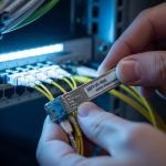
Solution: Measure fiber loss from MPO/LC endpoints with a light source and power meter. Verify patch panel mapping, then clean connectors and re-seat modules. If available, check interface counters for CRC errors and optical diagnostics for RX power.
Pitfall 2: Intermittent link drops in high-temperature cabinets
Root cause: Using commercial temperature optics in environments that exceed vendor limits. Laser bias and receiver sensitivity can drift with temperature, and elevated cabinet temps accelerate aging.
Solution: Confirm cabinet ambient and module temperature range. Replace with extended-temperature SKUs and improve airflow or thermal design. In some deployments, moving from 25G SR to 10G LR over SMF can increase link margin and reduce receiver stress.
Pitfall 3: “DOM alarm” warnings or module not recognized
Root cause: DOM parameter mismatch, unsupported alarm thresholds, or platform optics authentication behavior. Some modules also report vendor-specific identifiers that trigger warnings.
Solution: Confirm the platform’s DOM expectations and check logs for “unsupported transceiver” messages. If warnings correlate with link issues, swap to a known-compatible model from your validation list. For monitoring, tune alert thresholds to your environment and avoid alert storms.
Pitfall 4: Connector contamination causing high error rates
Root cause: LC ferrules not cleaned before insertion; industrial dust and vibration cycles bring contaminants back into the optical path.
Solution: Use an approved fiber cleaning kit, inspect with a microscope/inspection scope, and clean both ends before reseating. Replace compromised patch cords; do not “reinsert and hope.”

Decision matrix: which industrial gateway transceiver fits your scenario?
Use this matrix during design and procurement. It weights distance, budget, compatibility risk, and temperature constraints that typically dominate industrial deployments.
| Reader profile | Best-fit option | Why | Key caveats |
|---|---|---|---|
| Short reach, cost-sensitive uplinks (legacy) | SFP 1G (SX) | Lowest power and cost for modest throughput | Limited bandwidth headroom; plan migration if you expect higher telemetry rates |
| Core uplinks with moderate distance | SFP+ 10G (SR or LR) | Balanced performance; widely validated in industrial switches | SR reach depends on MMF grade; LR SMF requires correct cabling and connector strategy |
| Modern aggregation needing higher throughput | SFP28 25G (SR or LR) | Higher capacity per port for edge compute and video/fast telemetry | Tighter compatibility and optics tolerances; validate BER and temperature behavior |
| High temperature or harsh cabinet environments | Extended-temp modules (any family, prefer LR over SMF when feasible) | Reduces thermal drift risk and link instability | Higher unit cost; ensure the switch supports the module family and DOM alarms |
| Vendor lock-in concerns | Validated third-party compatible optics with DOM tested | Lower procurement cost without sacrificing stability | Must be validated per switch model and firmware version |
Which Option Should You Choose?
If you are upgrading an existing industrial gateway design with stable 10G uplinks and mixed vendor hardware, choose SFP+ 10G first because it tends to have the widest compatibility coverage and mature deployment experience. If you are planning for higher telemetry density, faster edge compute, or you are redesigning aggregation from scratch, choose SFP28 25G but only after you validate fiber grade, measured link loss, and temperature behavior during a pilot. If your distances are moderate but reliability is paramount and you can standardize cabling, prefer LR over SMF for more optical budget margin and fewer MMF-related surprises.
Next step: align your transceiver choice with your monitoring and maintenance workflow by reviewing your optical diagnostics and alerting strategy in fiber-optic-link-budget-and-dom-monitoring.
FAQ
What is an industrial gateway transceiver, and why does it fail?
An industrial gateway transceiver is the pluggable optical module that converts Ethernet electrical signals to fiber optics for uplinks to switches or routers. Failures usually come from connector contamination, insufficient optical budget, temperature stress, or switch compatibility policies (DOM/authentication).
Should I choose SR or LR for an industrial IoT gateway?
Choose SR (typically 850 nm) when you have short runs and verified MMF grade (OM3/OM4) with measured insertion loss. Choose LR (typically 1310 nm) when you need more budget margin, longer runs, or you want to reduce MMF grade sensitivity across patch panels.
Do I need DOM for industrial monitoring?
DOM is highly recommended if you want proactive maintenance. It enables you to track RX optical power and module health, which can help detect degradation before a hard outage. However, verify your platform’s DOM support and alert handling to avoid false alarms.
Can I use third-party transceivers with industrial switches?
Often yes, but only after validating compatibility with your exact switch model and firmware. Some platforms accept compatible optics but warn on identifiers, while others restrict optics via authentication. The safest approach is to pilot-test the module in your cabinet and confirm stable link counters and DOM readings.
How do I troubleshoot intermittent link drops quickly?
First check optical diagnostics (RX power, temperature) and interface error counters for CRC/FCS patterns. Then clean and inspect connectors with an inspection scope, verify patch panel mapping, and confirm that the transceiver temperature is within the module’s rated range for the cabinet environment.
What temperature rating should I plan for?
For industrial cabinets exposed to heat or outdoor enclosures, choose extended-temperature optics (commonly -40 to 85 C variants) rather than commercial-grade modules. Also verify cabinet ambient and airflow; module rated temperature does not replace poor thermal design.
Author bio: I design and deploy industrial Ethernet and fiber transport systems, including optics validation, DOM-based monitoring, and field troubleshooting under real plant constraints. I focus on reducing tech debt by enforcing compatibility checks, measurable link budgets, and operational playbooks.