A fiber link is often the difference between a stable Industrial IoT data path and a field failure that takes hours to isolate. This article helps network and automation engineers choose an industrial gateway transceiver for real gateway deployments, covering optics specs, switch compatibility, diagnostics, and commissioning steps. You will also get troubleshooting patterns for common link-down causes and a realistic cost and TCO view.
What an industrial gateway transceiver must do in the field
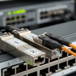
Industrial gateways typically aggregate sensors, meters, cameras, and PLC telemetry, then forward traffic to plant networks or cloud via fiber. Your transceiver choice must match the access switch optics, the fiber plant loss budget, and the harsh operating conditions inside cabinets. In practice, the transceiver becomes part of your reliability chain: it must survive temperature swings, vibration, and power cycling without degrading eye safety or BER targets. Per IEEE 802.3 Ethernet PHY requirements, link quality is not optional; it is measurable via link status, error counters, and vendor diagnostics. Source: IEEE 802.3
Key interface realities: data rate, optics type, and connector
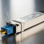
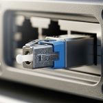
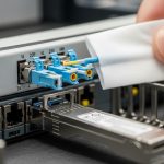
Start with the gateway uplink data rate and the switch port type. Most industrial deployments use 1G, 2.5G, or 10G Ethernet, with fiber optics chosen for EMI immunity and distance. Common optics families include 10G SR (multi-mode, short reach) and 10G LR (single-mode, longer reach). Connector type matters for install time: LC is common for SFP/SFP+ and SFP28; MPO/MTP appears on higher density multi-fiber modules like QSFP. Always verify whether the gateway uses an SFP, SFP+, SFP28, or QSFP slot and whether the switch expects the same form factor.
Diagnostics and manageability: DOM and alarms
Field engineers usually care more about optical power and temperature than about marketing reach numbers. Digital Optical Monitoring (DOM) provides real-time TX power, RX power, laser bias current, and sometimes temperature and voltage, depending on the module. When available, DOM lets you detect marginal optics before the link fails, which reduces mean time to repair. Many enterprise switches and industrial managed switches can read DOM; some do not, or they show limited fields.

Core specs that decide compatibility and reach
Engineers often treat reach as a single figure, but real installations depend on the fiber type, core size, patch cords, splices, and connector cleanliness. Use the transceiver spec sheet plus your measured link loss to confirm margin. Below is a practical comparison for the most common industrial gateway optics choices used with 10G uplinks.
| Transceiver type | Standard wavelength | Typical reach | Fiber type | Connector | Power use (typ.) | Operating temperature |
|---|---|---|---|---|---|---|
| SFP+ 10G SR | 850 nm | 300 m (OM3) / 400 m (OM4) | Multi-mode | LC | ~1.0 to 1.8 W | -40 C to 85 C (varies by vendor) |
| SFP+ 10G LR | 1310 nm | 10 km | Single-mode | LC | ~1.5 to 2.5 W | -40 C to 85 C (varies by vendor) |
| SFP28 25G SR | 850 nm | 70 m (OM3) / 100 m (OM4) | Multi-mode | LC | ~1.5 to 2.7 W | -20 C to 70 C or -40 C to 85 C (varies) |
| QSFP+ 40G SR4 | 850 nm | 100 m (typ.) | Multi-mode | MPO/MTP | ~4 to 7 W | -40 C to 85 C (varies) |
Examples of widely used optics families include Cisco SFP-10G-SR style modules and third-party equivalents such as Finisar FTLX8571D3BCL (10GBASE-SR) or FS.com SFP-10GSR-85 variants. Always confirm compliance with the specific host switch PHY requirements and connector keying. Source: Cisco Support
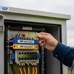
Pro Tip: In brownfield plants, the dominant cause of “it should work” link failures is patch cord loss and dirty endfaces, not transceiver reach. Before swapping optics again, measure end-to-end loss with a power meter and inspect/clean LC or MPO connectors using proper lint-free procedures and a microscope.
Decision checklist for an industrial gateway transceiver
Use this ordered list during procurement and commissioning. It is faster than trial-and-error in the field.
- Distance and fiber type: Determine single-mode vs multi-mode, then compute link loss using actual patch cord lengths, splice count, and connector loss (not only the transceiver reach).
- Switch and gateway compatibility: Confirm the exact slot type (SFP vs SFP+ vs SFP28 vs QSFP) and the switch port speed mode. Some hosts require specific electrical characteristics or vendor-coded EEPROM behavior.
- DOM support and monitoring: Verify whether the host reads DOM fields and whether alarms propagate to your monitoring stack.
- Operating temperature and enclosure airflow: Industrial optics may be rated to -40 C to 85 C, but the gateway cabinet can exceed that near heaters. Check worst-case ambient and airflow.
- Budget and power: Higher-speed optics can increase power and heat. If you run dozens of links, power and cooling become part of TCO.
- Vendor lock-in risk: If you rely on vendor-specific compatibility, plan spares strategy and validate third-party modules in a lab before scaling.
Deployment scenario: 10G leaf-spine with gateway uplinks
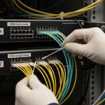
Consider a 3-tier data center leaf-spine topology inside a manufacturing site: 48-port 10G ToR switches at the access layer, aggregated to a pair of 100G spine switches. Each industrial gateway uplinks at 10G over fiber to an access switch. The plant uses OM4 multi-mode trunk runs from row cabinets to the switch room, with typical patch cord lengths of 2 m and about 6 connectors per path. Engineers target a conservative margin of 3 dB to account for cleaning variability and aging. In this scenario, 10G SR modules for OM4 can be viable when the total measured loss stays within the vendor’s link budget; otherwise, moving to a 10G LR single-mode design prevents intermittent errors during temperature swings.

Common mistakes and troubleshooting patterns
Even experienced teams hit predictable failure modes. Here are field-tested checks.
Link down after install: wrong fiber type or bad patch cord
Root cause: Multi-mode optics installed with single-mode fiber, or vice versa; or using the wrong patch cord type and connector geometry. Solution: Verify fiber type labeling, trace the run, and confirm connector endface cleanliness. Then test a short known-good patch cord between the gateway and a spare switch port.
Flapping link: excessive optical loss or dirty connectors
Root cause: TX power and RX power margins are too tight; endfaces have contamination, causing reflections and elevated BER under vibration. Solution: Use DOM to read RX power. Clean both ends with approved procedures and re-measure. If RX power remains marginal, replace patch cords or revise the loss budget by moving to a higher-reach optic.
Works at room temperature but fails in a hot cabinet
Root cause: Temperature rating mismatch or insufficient airflow around the gateway. Some optics tolerate -40 C to 85 C, but the host module cage thermal profile can push effective temperature higher. Solution: Validate with thermal measurements at the gateway during worst-case ambient. Improve cabinet airflow or upgrade to industrial-rated optics with documented temperature performance.
Alarm storms in monitoring: DOM not supported or misread
Root cause: Host firmware expects specific EEPROM values; third-party optics may provide DOM fields with different scaling or missing alarms. Solution: Confirm DOM interoperability with the exact gateway model and firmware version. If needed, configure monitoring to tolerate missing DOM fields or use modules that match the host’s expectations.
Cost and ROI note: OEM vs third-party optics
In typical procurement, OEM-style industrial optics often cost more per module but can reduce commissioning time due to consistent compatibility. Third-party modules can be materially cheaper, especially for large spares pools, but they require validation on the exact gateway and switch models to avoid RMA churn. For TCO, include labor: each failed link can consume technician hours for cleaning, measurements, and rework. Power and cooling impact also matter; a switch with many 10G or 25G uplinks may add measurable heat load across cabinets, affecting fan duty cycles and long-term reliability. Plan a staged rollout: validate in a lab, then deploy in one production zone before scaling.
FAQ
How do I confirm the right industrial gateway transceiver form factor?
Check the gateway’s optics cage labeling and the port documentation for SFP, SFP+, or SFP28. Then confirm the switch port speed mode and whether it supports that optics family. If you share the gateway model and uplink speed, you can map the exact module family.
Is 10G SR enough for most plant distances?
It can be, if you have OM4 multi-mode fiber and the measured link loss stays within the module’s budget with margin. If you see frequent flaps or marginal RX power, switch to a longer reach option or correct the patch cord and connector loss.
What does DOM change for industrial monitoring?
DOM enables visibility into TX power, RX power, and module temperature, which helps you detect degradation before total failure. Not every host surfaces all DOM fields, so validate monitoring behavior with your gateway and switch firmware.
Can third-party industrial gateway transceivers work with any switch?
They often do, but not always. EEPROM coding and DOM behavior can differ, and some hosts enforce compatibility checks. Validate a sample batch on the exact switch and gateway firmware before buying spares at scale.
What is the fastest troubleshooting order when the link is down?
First verify fiber type and connector seating, then inspect and clean endfaces. Next check optical power via DOM and confirm the switch port speed negotiation. Finally, swap with a known-good module and patch cord to isolate whether the issue is optics, fiber, or host compatibility.
Should I stock spares, and how many?
For critical uplinks, stock at least one spare per link group or per site, plus additional units for high-risk zones. Your spares count should reflect historical failure rates, lead times, and whether you can quickly source compatible replacements.
Choosing an industrial gateway transceiver is an engineering task: match optics to fiber and host behavior, then validate with measurements and monitoring. Next, review fiber link budget to convert vendor reach into a field-ready loss budget you can trust.
Author bio: I design and commission fiber transport for industrial networks, using DOM telemetry, loss budgets, and thermal validation on real cabinets. I also support field teams with rapid isolation workflows for link failures and compatibility issues.