In real networks, SFP links often “mysteriously” flap, drop to lower speeds, or fail to light up after maintenance. This happens far more often than firmware bugs: connector contamination changes optical power and can trigger link margin collapse. This guide helps operations and field engineers apply IEC 61300-3-35 cleanliness testing principles to stop dirty-connectors from breaking transceivers and optics. You will also get a practical checklist, troubleshooting patterns, and ROI expectations for cleaning and inspection workflows.
Why IEC 61300-3-35 cleanliness testing predicts SFP failures
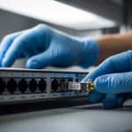
Optical connectors are tiny optical systems where micron-scale residue and scratches can scatter light or block the core. Under typical 10G/25G/40G SFP operating conditions, even a small amount of contamination can reduce received power by several dB, pushing the transceiver beyond its link budget. IEC 61300-3-35 defines test methods and acceptance criteria for assessing cleanliness and contamination risk on fiber optic connectors. In practice, teams use these methods to standardize inspection, cleaning, and pass/fail decisions before blame moves to optics or switches. IEC webstore page for IEC 61300-3-35

For SFP modules, the failure mode is typically physical-layer: reduced optical power, increased bit errors, and link negotiation instability. Many deployments also see “it worked yesterday” events after patching, cabinet moves, or endface exposure during swaps. IEC-aligned processes reduce variability by making inspection and cleaning repeatable. Field experience shows that the same pair of connectors can pass on one day and fail after a single uncontrolled handling window.
Key specs and how cleanliness impacts your link budget
Cleanliness testing is not abstract; it directly affects optical power, return loss, and error rates. Below is a practical comparison of common SFP optical classes and what contamination tends to break first: link margin (receive power) and sometimes reflections (return loss), depending on connector geometry and dust type. Note that exact limits vary by vendor and module revision, so always confirm against the specific transceiver datasheet and the host switch optics requirements.
| Module class (examples) | Typical wavelength | Reach (typical) | Connector | Operating temp | Cleanliness sensitivity |
|---|---|---|---|---|---|
| SFP SR (e.g., Cisco SFP-10G-SR, Finisar FTLX8571D3BCL) | 850 nm | ~300 m over OM3 | LC | 0 to 70 C (varies) | High for dirty LC endfaces; core scattering |
| SFP LR (e.g., 10G LR) | 1310 nm | ~10 km on SMF | LC | 0 to 70 C (varies) | Medium to high; dust adds insertion loss and errors |
| SFP+ active optical or long-reach variants | varies | 1 km to 80 km | LC/SC (varies) | varies | High; margin is tighter at longer distances |
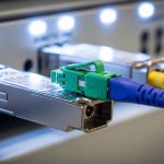
In a typical 10G SR link, teams often see failures that correlate with connectors that were left uncapped or exposed during patch panel work. If you are using OM3/OM4 and LC connectors, the dominant issue is usually insertion loss increase from dust and micro-scratches. IEC-aligned inspection targets the root cause: contamination visibility on the ferrule endface. [Source: IEEE 802.3 (10GBASE-SR/SR/LR optical layer expectations)] IEEE 802.3 standards page
Pro Tip: If you only clean and never re-inspect, you will eventually “clean the wrong thing.” In field audits, technicians frequently clean the outer endface while leaving contamination in the fiber tip region or reintroducing debris during re-capping. IEC-style inspection before and after cleaning is what breaks that failure loop.
Deployment scenario: leaf-spine data center patching that triggers IEC-style failures
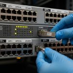
Consider a 3-tier data center leaf-spine topology with 48-port 10G ToR switches using SFP+ SR optics uplinks over OM4. During a weekend maintenance window, the team replaces 16 patch cords and reassigns 4 uplinks; each change exposes LC endfaces for roughly 30 to 90 seconds while labels are applied. Monday morning, link LEDs show intermittent flaps and the switch logs “loss of signal” events on 7 of 20 affected ports. After switching to an inspection-first workflow aligned to IEC 61300-3-35, the team finds soot-like residue and fine dust on 5 LC pairs; cleaning and re-testing restores stable link operation. Real-world lesson: speed of patching without endface protection is the hidden variable behind optical-layer failures.

Selection criteria and decision checklist for cleanliness control
Use this ordered checklist when choosing an inspection/cleaning process that maps to IEC 61300-3-35 expectations. It is designed for day-to-day operations, not lab-only validation.
- Distance and margin sensitivity: longer reach modules and higher lane rates have less tolerance for added loss.
- Switch and transceiver compatibility: verify the host tolerates your optical power levels and that vendor guidance allows your cleaning method.
- Connector type and geometry: LC vs SC, APC vs UPC polishing, and ferrule condition change what “pass” looks like.
- DOM and diagnostics support: confirm the SFP provides reliable digital diagnostics (Tx/Rx power) so you can correlate cleanliness fixes to optical metrics.
- Operating temperature and airflow: cabinets with high dust loads require stricter handling discipline and more frequent inspection intervals.
- Operating procedure maturity: ensure training includes “inspect before clean” and “inspect after clean,” not just microfiber wiping.
- Vendor lock-in risk: prefer systems that support standard inspection outputs and cleaning consumables; avoid proprietary-only workflows where possible.
Common mistakes and troubleshooting tips for dirty SFP connectors
Below are frequent failure modes and what to do next. These are grounded in what field teams see when links refuse to stabilize.
- Mistake 1: Cleaning without inspection
Root cause: technicians wipe visible contamination but leave residue at the fiber tip or scratch debris that persists.
Solution: inspect with a fiber endface scope, clean using approved consumables, then inspect again before reconnecting. - Mistake 2: Reusing one wipe across multiple ports
Root cause: contaminated wipes spread dust between connectors, making “new” failures appear after cleaning.
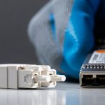
Solution: use single-use wipes or lint-free swabs per connector; follow vendor instructions for pressure and stroke direction. - Mistake 3: Leaving dust caps off during patching
Root cause: airborne particles settle on exposed ferrules; residue becomes optically active once mated.
Solution: keep caps on until the moment of mating; stage patch cords in sealed packaging when possible. - Mistake 4: Assuming the transceiver is bad first
Root cause: swapping modules masks the contamination issue because the same dirty connector pair remains.
Solution: move the same transceiver to a known-clean port, then test the original port with a known-good transceiver to isolate connector cleanliness.

Cost and ROI: cleaning programs versus repeated optics swaps
Inspection scopes and cleaning kits vary widely by vendor, but a practical estimate for an enterprise is often $200 to $1,000 per inspection tool plus recurring consumables. The recurring cost is usually far lower than frequent transceiver replacements and truck rolls. In many operations teams, a cleanliness program reduces optics RMAs and port flaps; even if you budget a conservative 1 to 3 hours of labor per major patch event, the avoided downtime and failed deployments typically dominate TCO. OEM optics may cost more (and sometimes require stricter handling), but third-party optics still fail the same way if connector endfaces are contaminated.
FAQ
Q1: What does IEC 61300-3-35 actually cover for connectors?
It focuses on standardized methods for assessing cleanliness and contamination on fiber optic connectors and ferrules. The goal is repeatable inspection and acceptance decisions that correlate with optical performance.
Q2: Do I need IEC 61300-3-35 compliance for every SFP link?
You do not need to “certify” every link, but you do need a consistent inspection and cleaning workflow. For higher-rate and longer-reach optics, adopting IEC-aligned practices is strongly justified.
Q3: How can I prove cleanliness fixed the issue?
Use transceiver digital diagnostics to compare Tx/Rx power and check error counters after re-cleaning and re-inspection. If possible, validate with an optical power meter and confirm stable link state over time.
Q4: Are LC connectors more problematic than SC for SFP deployments?
Both can fail, but LC density in patch panels increases the chance of mishandling and endface exposure. The failure mechanism is the same: dust and scratches degrade insertion loss and sometimes reflections.
Q5: What is the fastest troubleshooting path when an SFP link flaps?
First, inspect both connector endfaces at the affected patch points. Second, clean and re-inspect; then isolate by moving the transceiver to a known-clean port and re-testing.
Q6: Can DOM help me catch cleanliness problems early?
Yes. A gradual Rx power decrease and increasing error rate can indicate added loss from contamination or micro-damage. DOM does not replace visual inspection, but it helps prioritize which ports to inspect first.
Dirty connector endfaces are a leading cause of SFP link instability, and IEC 61300-3-35 provides the standard mindset for inspection-driven acceptance. Next step: build an