If your hybrid cloud rollout keeps stalling on link bring-up, it is usually not the switch configuration. It is the optical transceiver choice: wrong wavelength, unsupported DOM, mismatched reach, or power/temperature margins that fail only after deployment. This guide helps network and data center engineers choose the right fiber optic transceiver for hybrid cloud environments, with practical checks you can run before you rack-and-stack.
Prerequisites that prevent bad optical buys
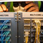
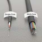
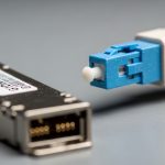
Before you compare part numbers, gather the inputs that actually determine whether an optical module will work in your hybrid cloud design. You need the exact switch model, transceiver form factor (SFP, SFP28, QSFP+, QSFP28, OSFP, CFP2/4), and the link type (Ethernet over fiber). You also need the planned fiber plant details: core diameter (single-mode vs multi-mode), connector type, and measured end-to-end loss.
For hybrid cloud, also confirm whether you are extending to a carrier or colocation fabric with different optics constraints. Many carrier handoffs enforce specific wavelengths and link budgets; your internal optics must match the far end. Finally, verify whether your switches require vendor-specific compatibility behavior around laser safety, digital diagnostics, and EEPROM provisioning.
Map your hybrid cloud link to the correct optical standard
Optical transceivers are not interchangeable by “data rate” alone. You must match the physical layer standard and wavelength to what both ends support, typically aligned to IEEE Ethernet physical layer definitions and vendor optics compatibility lists. For example, 10GBASE-SR uses multi-mode fiber at 850 nm, while 10GBASE-LR uses single-mode fiber at 1310 nm. For 25G, 100G, and beyond, the reach and lane structure change, so you cannot assume that “25G SR is the same as 25G SR” across vendors.
Quick mapping rules
- Multi-mode (MMF) at 850 nm is usually short reach (typical enterprise and data center top-of-rack).
- Single-mode (SMF) at 1310 nm or 1550 nm supports longer reach (common for inter-site hybrid cloud links).
- Wavelength matters: SR (850), LR (1310), ER (1550) are different optics families.
- Connector type matters: LC dominates in modern data centers; some legacy gear uses SC.
Use the IEEE Ethernet physical layer references to anchor your choices. For example, 10GBASE-SR and 10GBASE-LR are defined in IEEE 802.3; vendor datasheets then specify optical power, receiver sensitivity, and DOM behavior that determine the real link budget. [Source: IEEE 802.3] and [Source: Cisco Optics Compatibility Documentation].

Compare reach, wavelength, and power using a real specs table
Once the standard is mapped, compare transceiver specifications that directly affect hybrid cloud uptime: wavelength, rated reach, optical budget (Tx power and Rx sensitivity), connector, and temperature range. Also check whether the module is specified for the same DOM interface your switch expects (e.g., digital diagnostic monitoring with I2C/MDIO-like access via the module). In field deployments, DOM mismatches can cause ports to flap or remain administratively down even when optics “appear” to insert correctly.
Reference comparison: common Ethernet optics used in hybrid cloud fabrics
The table below shows representative modules across typical data center and inter-site designs. Actual values vary by vendor and product revision, so always validate against the exact datasheet you plan to buy.
| Module type | Data rate | Wavelength | Typical reach | Fiber / core | Connector | DOM | Operating temp |
|---|---|---|---|---|---|---|---|
| SFP-10G SR (example: Cisco SFP-10G-SR) | 10G | 850 nm | ~300 m (MMF) | OM3/OM4 | LC | Supported | 0 to 70 C typical |
| SFP-10G LR (example: Cisco SFP-10G-LR) | 10G | 1310 nm | ~10 km (SMF) | OS2 | LC | Supported | 0 to 70 C typical |
| SFP+ 25G SR (example: FS.com SFP-25G-SR) | 25G | 850 nm | ~70 m (OM3) / ~100 m (OM4) | OM3/OM4 | LC | Supported | 0 to 70 C typical |
| QSFP28 100G SR4 (example: Finisar FTLX8571D3BCL) | 100G | 850 nm | ~100 m (OM4 typical) | OM4 | LC (12-fiber MPO) | Supported | -5 to 70 C typical |
| QSFP28 100G LR4 (example: vendor 100G LR4) | 100G | ~1310 nm (4 lanes) | ~10 km (SMF typical) | OS2 | LC | Supported | -5 to 70 C typical |
For hybrid cloud, the “reach” spec is only half the story. You must compute the link budget using Tx launch power, receiver sensitivity, fiber attenuation at the wavelength, connector insertion loss, and splices. If your planned distance is close to the rated reach, hybrid cloud deployments often fail during seasonal temperature swings or after patching changes increase loss.
Pro Tip: In the field, the most common “mystery” failure is not the transceiver type—it is a too-optimistic assumption about fiber loss. If you do not have OTDR traces for the exact patch cords and splices in the path, treat rated reach as a best-case ceiling and add margin for aging, dust, and re-termination.
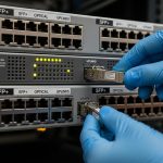
Validate switch compatibility and DOM behavior before you ship
Hybrid cloud networks are frequently multi-vendor: switches, optics, and sometimes routers in the carrier edge. Many platforms enforce transceiver compatibility via EEPROM fields and vendor-specific calibration. Start by checking the switch vendor’s optics compatibility list, then verify that the module supports the required DOM interface and that it reports vendor ID, wavelength, and transceiver type exactly as the platform expects.
What to check in practice
- Form factor: SFP vs SFP+ vs SFP28 vs QSFP28 vs OSFP must match the port.
- Speed and lane mapping: 100G SR4 uses four lanes; ensure the switch port expects SR4, not a different 100G family.
- DOM support: confirm the module is programmed for digital diagnostics and that your switch can read temperature, Tx bias/current, and optical power.
- Vendor lock-in risk: if the platform blocks non-approved optics, budget time for validation and consider OEM or “verified compatible” optics.
- Laser safety: confirm compliance for your environment; ensure modules are intended for the target wavelength and class.
Field engineers often discover this during staging: the port may come up at low link speed, remain in an error-disabled state, or show “unsupported transceiver.” That is why compatibility checks must be part of the hybrid cloud implementation checklist, not an afterthought.

Use a decision checklist engineers actually follow
When you are choosing transceivers for hybrid cloud, the “right” answer is the one that passes operational constraints over time, not the one with the highest advertised reach. Use this ordered checklist to reduce rework and port downtime.
- Distance and link budget: measure or estimate fiber loss at the wavelength, include connectors and splices, and add margin.
- Switch and port compatibility: match form factor and ensure the exact transceiver family is supported.
- Budget vs reach tradeoff: if you are near the ceiling, prefer a longer-reach optics family or improve fiber cleanliness/patching.
- DOM and monitoring: confirm telemetry fields your monitoring system expects; ensure thresholds do not immediately trigger alarms.
- Operating temperature: check module spec and your rack airflow; hybrid cloud sites may run hot in colocation.
- Connector and fiber type: LC vs MPO, OM3 vs OM4 vs OS2; verify before ordering.
- Vendor lock-in risk: if you need third-party optics, test a small batch first and document the acceptance criteria.
- Spare strategy: keep a minimum spares pool for the most critical link types (especially inter-site SMF optics).
For authority and baseline expectations, keep the IEEE Ethernet physical layer definitions handy and cross-check with vendor optics datasheets for exact optical power and receiver sensitivity figures. [Source: IEEE 802.3] and [Source: manufacturer SFP/QSFP datasheets].
Implementation steps for a hybrid cloud rollout (rack, test, and monitor)
After you select the transceiver families and confirm compatibility, you need a repeatable deployment process. The goal is to bring links up quickly, then validate performance using optical diagnostics and error counters.
Step-by-step actions
- Stage the optics: label each module by wavelength family, speed, and intended link ID; store in ESD-safe packaging and avoid touching ferrules.
- Clean connectors: before insertion, clean LC/MPO end faces with lint-free wipes and alcohol-approved cleaning tools; inspect with a scope if you have one.
- Insert and verify link state: on the switch, check transceiver status, speed negotiation, and interface up/down transitions. Ensure the port recognizes the DOM fields.
- Validate optical power: read DOM values for Tx and Rx optical power, and confirm they sit within vendor-recommended thresholds.
- Run traffic and monitor errors: generate sustained traffic (for example, iperf3-equivalent at line rate within your lab constraints) and watch CRC, FCS errors, and link flap events.
- Lock configuration: once stable, document the exact optics part numbers and firmware/software versions used for that hybrid cloud link.
In a multi-site hybrid cloud, this documentation becomes your operational moat. When an outage happens months later, you can correlate DOM drift and error counters to a specific transceiver family rather than guessing across many variables.

Common mistakes and troubleshooting tips
Even with correct planning, hybrid cloud optics can fail. Below are the top failure modes engineers see in production, with root causes and fixes.
Failure point 1: Port shows “unsupported transceiver” or stays down
Root cause: form factor mismatch, wrong transceiver family (for example, SR vs LR), or EEPROM fields not accepted by the switch. Some platforms enforce strict part-number validation.
Solution: confirm the port type and speed (including lane mapping for 100G), then verify your module is on the vendor compatibility list. If you are using third-party optics, test in a staging rack first and capture the exact error logs.
Failure point 2: Link comes up but errors spike under load
Root cause: dirty connectors, marginal optical power due to underestimated loss, or fiber type mismatch (OM3 vs OM4 vs OS2). This often appears only when traffic is sustained.
Solution: clean and re-seat connectors, verify fiber type labeling, and re-check DOM optical power values. If you have OTDR data, compare measured attenuation to your budget; consider swapping to a higher-margin optics family (e.g., LR instead of “near-ceiling” SR).
Failure point 3: Intermittent link flaps during temperature changes
Root cause: module operating outside its temperature spec for the rack environment, or airflow problems causing thermal drift in laser bias/current.
Solution: measure inlet/outlet temps at the rack, verify module temperature range, and improve airflow. If needed, move to modules specified for wider temperature ranges or adjust placement to reduce heat soak.
If you want a structured approach, align your troubleshooting with the physical-layer expectations in IEEE 802.3 and follow vendor transceiver troubleshooting guides. [Source: IEEE 802.3] and [Source: vendor optics troubleshooting documentation].
Cost & ROI note for hybrid cloud optics
Optics pricing varies widely by form factor and reach. As a realistic range, OEM-compatible optics often cost roughly 1.2x to 2.5x third-party options for the same nominal standard, while third-party modules can be cheaper but require validation overhead. For example, an enterprise 10G SR SFP+ might land in the low tens of dollars for third-party and higher for OEM; 100G QSFP28 SR4 or LR4 is commonly much higher and can dominate optics spend during scale-up.
TCO is not just purchase price. Include cleaning tools, spares inventory, downtime risk, and the engineering time spent on compatibility testing. A practical ROI model: if a third-party optics batch reduces unit cost by 20% but increases validation time by weeks or causes one inter-site outage, the savings can evaporate fast. For hybrid cloud, where inter-site links are operationally critical, it is often rational to buy OEM or “verified compatible” optics for the longest-reach segments and use lower-cost optics within the controlled data center fabric.
FAQ
How do I know whether to use SR or LR for hybrid cloud?
Use SR when your path is within the multi-mode reach at 850 nm, and use LR when you need single-mode reach at 1310 nm. In hybrid cloud, inter-site links are usually SMF, so LR or ER is more common. Always validate with your measured link budget and connector/splice losses.
Can I mix third-party optics with OEM switches in a hybrid cloud?
Sometimes yes, but compatibility is platform-specific. Check the switch vendor’s optics compatibility list and verify DOM support behavior. Stage-test a small batch in the same rack airflow and fiber patching conditions before scaling.
What DOM fields matter for operations?
At minimum, monitor temperature, Tx bias/current, and Tx/Rx optical power. If your monitoring system relies on thresholds, confirm that the module reports values in expected units and ranges. Misaligned thresholds can create false alarms or hide real degradation.
Why does a link fail only after a patch change?
Patch changes often introduce extra loss or dirt at connectors. Even a small increase in insertion loss can push you over the optical margin, especially near rated reach. Clean connectors, re-scope end faces, and re-check DOM optical power after each change.
What is the safest way to choose spares for hybrid cloud optics?
Keep spares for the most critical link types: inter-site SMF optics (LR/ER families) and the highest utilization fabric segments. Store modules properly and label by part number, wavelength family, and intended link ID so replacements are fast and traceable.
Do I need OTDR for every fiber run?
Not always, but OTDR is valuable when you are close to reach limits or when multiple re-terminations happened over time. If you cannot get OTDR traces, compensate by using conservative link budgets and adding margin. For hybrid cloud inter-site design, more measurement usually means fewer surprises.
If you want to make hybrid cloud networking predictable, treat transceiver selection like a system design problem: standard mapping, link budget math, and switch compatibility validation. Next, review transceiver DOM monitoring for hybrid cloud to build monitoring thresholds that catch drift before outages.
Author bio: I have deployed and troubleshot optical transceiver links in multi-site data centers, focusing on DOM telemetry, link budgets, and switch compatibility validation. I write from the perspective of what actually gets field-tested during rollouts and change windows.