AI clusters fail in predictable ways: marginal optics, wrong fiber type, and mismatched transceiver profiles that only show up under load. This guide helps network engineers and field technicians select high-performance optics for 25G to 400G fabrics, with practical compatibility checks and troubleshooting patterns. You will also get a step-by-step implementation plan, a decision checklist, and a specs comparison table.
Step-by-step prerequisites for selecting high-performance optics
Before you buy transceivers, gather the physical layer facts that determine whether links will train and stay stable. This is especially important for AI traffic, where microbursts and long steady-state utilization stress receiver sensitivity and thermal margins. If you skip inventory and budget time, you will end up swapping optics during maintenance windows.
Prerequisites (collect these items first)
- Switch and line card model numbers: e.g., Cisco Nexus 93180YC-FX3, NVIDIA Spectrum-based leafs, Arista 7280R, or Broadcom-based whitebox platforms.
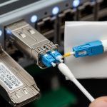
- Transceiver form factor and speed plan: SFP28 (25G), QSFP28 (100G), OSFP (400G), or similar.
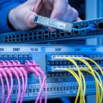
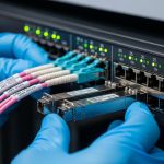
- Fiber plant details from as-built drawings and OTDR runs: core type (OM3/OM4/OS2), length, patch panel losses, and connector cleanliness state.
- Expected ambient temperature inside the rack (front-to-back airflow matters): record inlet temps at the switch.
- Optics vendor constraints: approved OEM list, “must support” DOM/EEPROM behavior, and any locked transceiver policy.
Expected outcome: You can map each intended link (server-to-leaf, leaf-to-spine, spine-to-core) to a specific wavelength, reach class, and connector type, before ordering.

Match wavelength and reach to the AI fabric topology
AI fabrics often use short-reach multimode for top-of-rack and sometimes single-mode for longer spine runs. Most 25G/50G/100G short-reach links in data centers use 850 nm multimode (SR/SR4 variants), while longer distances use 1310 nm or 1550 nm single-mode (LR/ER/ZR variants). The IEEE 802.3 family defines the electrical and optical link behavior; vendor datasheets define actual reach with real optics and module power.
Rule of thumb for common AI link distances
- 0–100 m on OM4: 100G SR4 and 25G SR can work with conservative margins if patch losses are controlled.
- 100–300 m on OM4: consider higher-grade multimode reach variants or move to single-mode.
- Above 300–500 m: plan on single-mode (OS2) optics to avoid multimode budget surprises.
Expected outcome: Each port gets a target optics class (wavelength + reach) that aligns with your physical plant and expected utilization profile.
Use a specs comparison table to avoid “it fits” ordering errors
Form factor alone does not guarantee compatibility. For high-performance optics, you must match data rate, lane count, receiver sensitivity class, transmit power class, connector type, and operating temperature. DOM support also matters for telemetry and automated monitoring, especially when you have hundreds of ports.
Key specs to compare across candidate modules
| Spec | Example Module A | Example Module B | Why it matters in AI clusters |
|---|---|---|---|
| Data rate | 100G (4x25G) QSFP28 | 25G SFP28 | Lane mapping and FEC assumptions change link training behavior |
| Wavelength | 850 nm | 1310 nm | Multimode vs single-mode determines budget and dispersion limits |
| Reach target | Up to ~400 m on OM4 (vendor dependent) | Up to ~10 km on OS2 (vendor dependent) | Wrong reach class can pass at boot and fail under load |
| Connector | LC | LC | Connector contamination causes intermittent CRC and retrains |
| DOM / telemetry | Supported (I2C/EEPROM) | Supported (I2C/EEPROM) | Enables thresholds for temperature, bias current, and optical power |
| Operating temperature | 0 to 70 C (typical for datacenter) | -5 to 70 C (typical) | AI racks run hot; margin prevents BER spikes |
| Standards basis | IEEE 802.3 100G SR4 class | IEEE 802.3 25G LR/ER class (vendor dependent) | Defines electrical/optical compliance and receiver behavior |
For concrete part examples, many deployments use OEM or compatible optics like Cisco SFP-10G-SR (older), and for 10G/25G/100G SR short reach you will see third-party offerings such as Finisar FTLX8571D3BCL (varies by speed generation) and FS.com SFP-10GSR-style modules (exact suffix depends on rate). Always verify the exact speed generation, DOM behavior, and wavelength/connector spec in the datasheet before ordering.
Expected outcome: You can eliminate incompatible candidates early and align each port to a spec-compliant optics class.
Pro Tip: In AI deployments, the “it links at 100% speed” moment can still hide a budget problem. Treat optical power and receiver margin as a first-class metric: enable DOM thresholds and watch for rising laser bias current and falling receive power over the first 72 hours after installation. A module that is healthy at day 0 can still drift into a high-BER state if patch loss or airflow is marginal.
Validate switch compatibility and DOM behavior before mass install
Many platforms load transceiver profiles from EEPROM and apply vendor-specific allowlists. Even when a module is standards-compliant, the switch may block it or report it as “unknown” for telemetry. DOM telemetry formats are not identical across vendors, so monitoring pipelines may break if you mix optics types without validation.
Checklist: compatibility validation steps
- Confirm port type and lane mapping: QSFP28 100G uses 4 lanes; SFP28 25G uses 1 lane.
- Confirm DOM support: read DOM via the switch CLI after insertion (example pattern: verify vendor name, part number, and optical power fields).
- Run a controlled link test: bring up one ToR pair, then generate sustained traffic (at least 10–20 minutes) to expose thermal and receiver margin issues.
- Validate alarm thresholds: ensure your monitoring system can parse the module’s DOM fields and alert on temperature and optical power drift.
Expected outcome: You avoid the most expensive failure mode: mass installation followed by port flaps, missing telemetry, or optics being administratively disabled.

Select the right module using an engineer decision checklist
Use this ordered checklist for high-performance optics in AI infrastructure. It reflects how engineers actually decide under time pressure: distance and budget first, then compatibility and telemetry, then thermal and operational constraints.
- Distance and fiber type: OM3/OM4/OS2, measured patch loss, and connector grade.
- Data rate and lane count: 25G, 50G, 100G SR4, 400G lane mapping (module-specific).
- Switch compatibility: OEM allowlist, transceiver profile support, and required DOM behavior.
- DOM support and monitoring integration: confirm fields your NOC needs (Tx power, Rx power, temperature, bias current).
- Operating temperature and airflow: verify module temperature range vs rack inlet temps.
- Budget and TCO: compare price per port, expected failure rates, and replacement logistics.
- Vendor lock-in risk: evaluate whether third-party optics are allowed and supported by your monitoring and change control.
Expected outcome: A documented, repeatable selection rationale that survives audits and reduces swap churn during outages.
Deploy in a real AI network environment with measurable checks
In a 3-tier AI data center leaf-spine topology with 48-port 100G ToR switches and 32-port 400G spine, you might run server-to-leaf at 100G SR4 over OM4 and leaf-to-spine at 400G LR4 over OS2. If your OTDR shows 1.2 dB worst-case patch loss per direction and your patch cords are cleaned and seated, you can hit stable link training with conservative receiver margins. After install, you should verify that CRC errors remain at 0 over the first 60 minutes and that DOM optical receive power does not trend downward more than a few dB over 72 hours. Pair this with airflow checks: ensure the rack inlet is within the module’s specified operating range to prevent temperature-induced bias current drift.

Common mistakes and troubleshooting for high-performance optics
Below are the top failure points seen in the field, with root causes and fixes. These apply to both OEM and compatible optics as long as the platform enforces profiles and the fiber plant is well managed.
Failure point 1: Link comes up briefly, then flaps under load
Root cause: Optical budget mismatch due to excessive patch loss, dirty connectors, or wrong fiber type (OM3 vs OM4) leading to insufficient receiver margin. The link can train at low stress, then fail as BER rises with sustained traffic.
Solution: Inspect and clean connectors, re-seat optics, then re-measure with OTDR and check DOM Rx power. If needed, replace with a module that has a higher supported reach class for your fiber plant.
Failure point 2: “Unknown transceiver” or missing DOM telemetry
Root cause: Switch compatibility profile mismatch or DOM field format differences across vendors. Some platforms require specific EEPROM fields or threshold formats to populate monitoring.
Solution: Validate with a single-port pilot using the exact module SKU approved for your switch model. If telemetry is required for NOC alerts, standardize optics vendor families or use OEM modules.
Failure point 3: Receiver sensitivity alarms or rising temperature events
Root cause: Rack airflow too weak or blocked, pushing module temperature beyond its operating envelope. Thermal drift can reduce receiver margin and increase error rates.
Solution: Verify inlet temperature and clear obstructions; confirm fan module health. Use DOM to trend temperature and optical power; if repeated, move the link to a port with better airflow or upgrade cooling.
Cost and ROI note for high-performance optics
In practice, optics pricing varies widely by speed and reach. As a rough planning range, third-party 25G/100G short-reach modules may cost less per unit than OEM, but OEM optics often reduce change-control friction and telemetry surprises. Over a year, TCO is dominated by downtime cost and labor for swaps: if a marginal optic causes a maintenance event, the labor and risk outweigh small unit price differences.
Operationally, prioritize the optics that match your fiber plant and your switch’s allowlist. When you standardize on one vendor family for a given speed class, you reduce troubleshooting time and improve mean time to repair.
FAQ
What makes optics “high-performance” for AI traffic?
For AI infrastructure, high-performance optics means stable receiver margin at high utilization, predictable DOM telemetry, and compliance with the relevant IEEE 802.3 link requirements. It also means thermal stability under sustained traffic, not just a datasheet reach number. [Source: IEEE 802.3 series documentation]
Can I mix OEM and third-party transceivers on the same switch?
Often yes for basic link operation, but telemetry and compatibility behavior can differ. Validate on a pilot port and confirm DOM parsing, alarm thresholds, and error counters behave consistently. [Source: switch vendor transceiver compatibility notes]
How do I calculate whether OM4 will support my 100G SR4 links?
Use the vendor reach guidance plus a real optical budget: fiber attenuation, patch cord loss, connector loss, and any additional margin for aging. Then verify with OTDR and DOM Rx power after installation. If you are near the edge, move to a longer-reach variant or single-mode.
What should I monitor in DOM to catch problems early?
Track Rx power, Tx power, module temperature, and bias current trends. Alert on drift patterns rather than single-point alarms, since marginal budgets show gradual deterioration. [Source: vendor DOM application notes and transceiver datasheets]
Do I need to worry about FEC or link training settings?
Many modern optics and switch ASICs handle FEC automatically, but you should confirm the platform’s supported optics modes. Misconfigured breakout modes or wrong lane mapping can still cause intermittent failures even if the optics are correct.
Are cleaning and inspection really worth it?
Yes: connector contamination is one of the most common causes of intermittent errors and link flaps in short-reach environments. A fiber inspection scope plus consistent cleaning reduces returns and speeds up troubleshooting.
High-performance optics succeed when the physical plant, switch compatibility, and monitoring are aligned end-to-end. Next, map your intended AI links to a specific optics class and run a one-port pilot before scaling. optics budget and DOM monitoring best practices
Author bio: