In day two operations, the fastest way to lose uptime is an optics mismatch that looks “link up” but behaves like a slow, unstable circuit. This guide helps network engineers and small data center operators understand how fiber speed negotiation works with SFP+ autonegotiation versus forcing speed, and what to verify before you blame cabling. You will get a field-ready decision checklist, a comparison table with real module examples, and troubleshooting patterns you can apply during a maintenance window.

How fiber speed negotiation behaves on SFP+ links
For SFP+ Ethernet, speed negotiation is typically tied to the link establishment process controlled by the host PHY and the optics module. In practical terms, the switch and transceiver exchange link capabilities and attempt to lock to a mutually supported mode; that is the “autonegotiation” path. When it succeeds, you get stable line rate, correct forward error correction behavior (if applicable), and predictable counters. When it fails, you may see link flaps, high error counts, or a link that settles at a lower speed than you expected.
Autonegotiation path (recommended for most networks)
With autoneg enabled, the PHY tries to agree on a common operating point using standard link negotiation logic defined by Ethernet PHY behavior and the relevant IEEE Ethernet standards. For 10GBASE-SR over multimode fiber, SFP+ modules typically operate at 10.3125 Gb/s line rate with the expected coding for 10G Ethernet. The key operational point is that the switch controls the final outcome; the optics must be compatible and within its electrical and optical limits.
Forced speed path (use only when you fully control both ends)
Forcing speed disables or bypasses negotiation for that parameter and relies on the assumption that both ends are configured identically. If the far end remains in autoneg, or if the optics are not fully compatible with the forced mode, you can end up with asymmetric expectations: one side transmits at one rate while the other side is prepared for another. Even when the link comes up, you may get subtle issues like CRC errors that only show up under load testing.
SFP+ autoneg vs forced speed: the spec-level comparison that matters
Engineers often focus on “10G vs 1G” and forget that optics and PHY are negotiated systems. The table below compares key properties you should check when deciding between autonegotiation and forced speed for SFP+ 10G links.
| Item to verify | Autonegotiation (SFP+) | Forced speed |
|---|---|---|
| Expected behavior | PHY agrees on a common mode during link training | Switch applies configured speed without negotiation |
| Operational risk | Lower risk when both ends support the same standards | Higher risk if the far end is not identically configured |
| Typical target rate | 10.3125 Gb/s for 10GBASE-SR | Must match exactly on both ends |
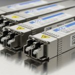
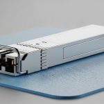
| Optics examples (10GBASE-SR) | Cisco SFP-10G-SR, Finisar FTLX8571D3BCL, FS.com SFP-10GSR-85 | Same optics may work, but only if forced mode matches PHY expectations |
| Connector | Commonly LC duplex | Commonly LC duplex |
| Typical fiber reach (MMF) | Often up to 300 m depending on OM3/OM4 and module specs | Same physical constraints apply; forcing does not improve reach |
| DOM / monitoring | Usually read by switch; helps diagnose power and temperature | Still advisable; forced speed does not replace optical health checks |
| Temperature range | Many modules specify 0 to 70 C (or industrial variants) | Same limits; forcing can worsen marginal links under thermal stress |

Real module compatibility checks you can do fast
Before you rely on either method, confirm that the optics support the same 10G Ethernet mode the switch expects. For example, a typical 10GBASE-SR SFP+ module such as Cisco SFP-10G-SR or Finisar FTLX8571D3BCL is designed around SR behavior over multimode fiber and expects the switch PHY to run the corresponding 10GBASE-SR signaling. Also confirm DOM support and that the switch does not apply an aggressive “unsupported optics” policy that can disable ports or throttle behavior.
Sources to anchor your expectations: IEEE Ethernet PHY behavior is documented across IEEE 802.3 series, and vendor datasheets specify optical budgets and electrical characteristics. See [Source: IEEE 802.3] and [Source: Cisco SFP-10G-SR datasheet], plus the module vendor datasheets for DOM and optical specs. For broader optics compatibility guidance, consult [Source: FS.com SFP+ product pages] and respected tech references like [Source: The Network Collective] (for operational patterns, not just marketing).
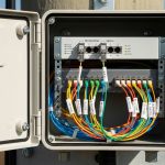
Deployment scenario: when forced speed causes the “slow link” outage
In a 3-tier data center leaf-spine topology with 48-port 10G ToR switches and 2 uplinks per ToR, an operator forced speed on the ToR side after migrating to a new transceiver batch. They targeted 10G on both ends, but the spine ports remained set to autoneg with a different default profile for optics. During the maintenance window, ports briefly went up, then settled into a degraded link state with elevated CRC and FCS drop counters. After swapping the far-end spine port configuration to match, the link stabilized and error counters dropped to baseline within 10 minutes, confirming the issue was negotiation mismatch rather than fiber cleanliness.
Pro Tip: If you must force speed in a controlled environment, still run a quick DOM sanity check: read laser bias current, received power, and module temperature during traffic spikes. Marginal optics can “look fine” at idle but fail during high BER stress, making forced speed seem like the root cause when it is actually hiding an optical budget problem.

Selection criteria: a decision checklist for negotiation mode
Use this ordered checklist during planning, not after the outage. It is designed to reduce negotiation ambiguity and maximize ROI by avoiding rework.
- Distance and fiber type: verify OM3/OM4 and expected reach versus module specifications; forcing speed does not change optical budget.
- Switch and PHY compatibility: confirm both ends support the same 10G mode and that the switch firmware interprets it correctly for SFP+.
- Negotiation policy: prefer autoneg unless you have a documented reason (special interoperability constraints).
- DOM support and thresholds: ensure the switch reads DOM and that alarms are enabled for temperature and optical power.
- Operating temperature: check module datasheet range; high temperature reduces optical margin and increases error probability.
- Vendor lock-in risk: third-party SFP+ modules can work, but validate with your switch model and firmware release; avoid surprises from “unsupported module” policies.
- Change control: if forcing speed, change both ends in one coordinated action and record the exact CLI settings.
Common pitfalls and troubleshooting tips
Most negotiation problems are configuration or marginal optics disguised as “link issues.” Below are concrete failure modes you can recognize quickly.
Pitfall 1: Far end stays on autoneg while you force locally
Root cause: asymmetric configuration leads to mismatch in link training expectations. Symptom: port flaps or comes up with unexpectedly high error counters. Fix: set both ends consistently, then verify with interface diagnostics (errors, FEC state if supported, and DOM readings).
Pitfall 2: Using the wrong fiber type or mismatched OM rating
Root cause: optical power budget is exceeded; negotiation might still complete at low margin. Symptom: errors increase with temperature or during sustained load. Fix: validate OM3 vs OM4, check connector cleanliness, and confirm receive power is within the module’s allowed range.
Pitfall 3: Forcing speed masks an optics compatibility limitation
Root cause: some switch firmware applies optics validation or lane/host expectations; forcing may allow link up but not proper performance. Symptom: link appears stable at idle, but traffic triggers CRC/FCS drops. Fix: test with a known-good module from the same vendor family, compare DOM values, and confirm the switch reports the correct transceiver type.
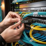
Pitfall 4: Dirty LC connectors after a swap
Root cause: micro-contamination increases insertion loss and raises BER. Symptom: sudden degradation after module replacement. Fix: inspect with a scope, clean using approved procedures, and re-seat fiber with consistent polarity and labeling.
Cost and ROI note: what you save and what you risk
In many markets, OEM SFP+ optics often cost roughly $80 to $200 per module, while reputable third-party options may land around $35 to $120 depending on reach and DOM support. The ROI comes from avoiding downtime: a single unstable link can cost far more than the optics delta when you factor in engineer time, incident response, and business impact. TCO should include failure rates under your temperature profile and the risk of firmware incompatibility; one “unsupported module” incident can erase savings quickly. If you are cost-optimizing, validate compatibility against your exact switch model and firmware version before scaling.
FAQ
Q: Does fiber speed negotiation apply only to SFP+?
A: The concept applies broadly to Ethernet links that support negotiation, but the exact mechanics depend on the PHY and optics behavior. With SFP+ 10G, you typically see it managed by the host PHY and switch port settings.
Q: Can forced speed ever be safer than autonegotiation?
A: It can be safer only when both ends are controlled and configured identically, and you have tested the exact optics-switch combination under load. In mixed or uncertain environments, autoneg is usually the safer default.
Q: What should I check first when the link comes up but performance is bad?
A: Start with error counters (CRC/FCS), then read DOM values for transmit power, receive power, and temperature. If DOM readings are within spec yet errors persist, inspect connector cleanliness and verify fiber type and polarity.
Q: Are third-party SFP+ modules compatible with all switches?
A: Not always. Compatibility depends on firmware optics validation policies and whether the module’s DOM and signaling behavior match expectations. Validate using your switch model and firmware version, not just “10G SR” in general.
Q: How do I decide between OM3 and OM4 for a new SFP+ rollout?
A: Use module reach specs plus a safety margin for worst-case connectors and aging. If you expect growth, OM4 can reduce optical stress and improve BER margin, which indirectly reduces the likelihood of negotiation-related surprises.
Q: Where can I find authoritative standards references?
A: Start with IEEE 802.3 for Ethernet PHY and link behavior, then use vendor datasheets for optics electrical and optical budgets. For operational patterns, consult reputable networking tech references like [Source: IEEE 802.3] and vendor documentation.
Fiber speed negotiation is less about “10G or not” and more about how link training and optical margin interact under real conditions. Next, use fiber optic transceiver compatibility to build a compatibility matrix for your switch models, firmware, and optics batches before you roll out changes.
Author bio: I run hands-on optics validation and port bring-up for enterprise and small data center networks, focusing on measurable link counters and DOM telemetry. I write from field deployments where the failure mode matters as much as the specification.