You are wiring a new rack, migrating uplinks, or fixing intermittent link drops, and the wrong fiber choice quietly burns time and budget. This article helps network engineers and field technicians make confident fiber selection decisions between multi-mode and single-mode—using real-world reach, optics behavior, and compatibility checks. You will leave with a practical checklist, common failure modes, and a ranking table to guide your next purchase.
Top 7 decisions in fiber selection: multi-mode vs single-mode
Fiber selection is not just about “distance.” It is about how light propagates, how transceivers modulate and tolerate dispersion, and how your switch optics expect the cable plant to behave. In practice, the choice affects SFP/QSFP compatibility, connector cleanliness, expected link margin, and even how often you will dispatch a tech for troubleshooting. Below are the seven highest-impact decisions we see during deployments.
Distance and reach: where multi-mode starts to fail
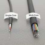
In short runs, multi-mode fiber (MMF) is often the fastest path to lower cost and simpler optics. But MMF reach shrinks quickly as data rates rise, because modal dispersion and launch conditions become harder to control. Single-mode fiber (SMF) generally maintains performance over longer distances because it supports essentially one propagation path.
How engineers estimate reach
Use the optics datasheet reach rating as your baseline, then apply a margin for patch cords, splices, and connector loss. For MMF, launch conditions are critical: the same transceiver can behave differently depending on whether the link is graded-index (OM3/OM4) versus older step-index variants. For SMF, the main limiter becomes chromatic dispersion and the transmitter/receiver sensitivity at the chosen wavelength.
- MMF best-fit: within campus, short data center rows, and structured cabling runs where patching dominates the budget.
- SMF best-fit: inter-building links, long spines, and any plan where you might later extend reach without re-cabling.

Data rate reality: 10G vs 25G vs 100G optics behavior
At 10G and 25G, MMF can be cost-effective, especially with OM4 and modern transceiver designs. At 40G and 100G, MMF still works in many data centers, but optics requirements tighten: you will see stricter requirements for fiber grade, launch mode, and link budget. SMF optics are typically more forgiving on distance and often become the safer long-term choice when your roadmap includes higher speeds.
Standards and why they matter
Transceivers commonly align to IEEE 802.3 Ethernet PHY requirements and vendor-specific link budgets. While the standard defines electrical/optical behavior at a high level, the detailed reach and power constraints are validated in vendor datasheets and measured with controlled test conditions. Translation: you must treat “rated reach” as a system result, not a property of fiber alone.
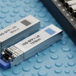
- MMF: frequently paired with SR optics (short-reach) for data center economics.
- SMF: frequently paired with LR/ER/ZR optics depending on distance and wavelength plan.
Fiber grade and wavelength: OM3/OM4 vs OS2 and the 850 nm vs 1310/1550 nm split
MMF grades like OM3 and OM4 are defined by optical bandwidth and modal performance, which directly affects high-speed reach. SMF commonly uses OS2 and relies on single-mode propagation, typically at 1310 nm or 1550 nm depending on the optics. If you mix grades or use the wrong cable type in a bundle, you can create links that pass certification once and fail under different transceiver temperature or aging conditions.
| Spec category | Multi-mode (OM3/OM4) | Single-mode (OS2) |
|---|---|---|
| Typical wavelength | 850 nm (SR optics) | 1310 nm or 1550 nm (LR/ER/ZR) |
| Typical connector ecosystem | LC (common), MPO for high-density | LC (common), SC/LC depending on plant |
| Reach behavior | Reach decreases faster as speed rises; sensitive to launch and patch cord quality | Reach stays more consistent; mainly constrained by optical budget and dispersion |
| Power and sensitivity impact | Higher sensitivity to transmitter/receiver optics and fiber grade | Better margin at longer distances with appropriate optics |
| Temperature range (typical) | Often -5 to 70 C for many transceivers; verify exact module | Often -5 to 70 C or extended variants; verify exact module |
| Best-fit scenario | Short-reach data center links and patch-heavy environments | Long-reach links, interconnects, and future speed headroom |
Note: Exact reach depends on transceiver model, fiber grade, connector cleanliness, and link budget. Always confirm with the optics datasheet and your installed plant measurements.
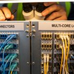
Switch and transceiver compatibility: don’t buy fiber in isolation
Fiber selection is incomplete without transceiver compatibility planning. Many vendors require specific fiber types (MMF vs SMF) and sometimes specific grades (e.g., OM4) for their “SR” optics. A common field problem is assuming a switch will “auto-negotiate” optics behavior; with fiber, the optics module type determines the physical layer, so the switch only sees a validated optical interface.
Concrete examples from the field
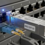
Engineers often pair Cisco SFP-10G-SR or similar SR modules with OM3/OM4 plants, while SMF options align to LR/ER models at 1310/1550 nm. Third-party optics can be compatible, but you must check DOM (Digital Optical Monitoring) behavior and whether the switch enforces vendor-specific diagnostics. DOM is not only about telemetry; it can affect how the switch interprets module health and link state.
- Operational check: verify transceiver part number, DOM support, and fiber type requirements before ordering cable.
- Lock-in risk: if your optics ecosystem is narrow, SMF or MMF decisions can force future replacements.

Link budget and measurement workflow: certify before you cut over
The most reliable fiber selection decisions are validated by measurement. During cutover windows, we routinely see links that fail not because the fiber type was wrong, but because connector endfaces were contaminated or losses exceeded expectations. Use an OTDR for SMF troubleshooting and an appropriate test plan for MMF (including end-to-end loss verification). For certification, follow the measurement workflow recommended by your cabling standard body and your testing equipment vendor.
What technicians measure
For MMF, focus on end-to-end attenuation and connector/splice loss as well as patch cord quality. For SMF, validate attenuation along the span and inspect for events (bends, micro-cracks, bad splices). In both cases, clean connectors are non-negotiable; a single dirty LC can erase your optical margin.
Pro Tip: If you are choosing between OM4 multi-mode and OS2 single-mode for a new high-density build, prioritize your test equipment and certification workflow. In many real deployments, the dominant failure mode is connector cleanliness and patch cord loss, not the theoretical bandwidth of the fiber grade—so the “best” fiber is the one you can reliably certify and maintain.
Installation constraints: bends, routing, and how plants age
Fiber selection must consider how the cable plant will be installed and maintained. Multi-mode patching in data centers often involves frequent moves and additions, which increases the chance of connector wear and bend-related attenuation. Single-mode plants can be easier to “set and forget” over longer spans, but they can still suffer from improper bend radius during installation.
Practical constraints that show up on site
Field engineers commonly manage bend radius limits, cable pulling tension, and rack layout. If your route includes tight corners, you need to coordinate with facilities for proper tray routing and slack management. Plan labeling and pathway segregation early so MMF and SMF do not get swapped in future maintenance.
- MMF advantage: often easier economics in short runs and dense rack-to-rack patching.
- SMF advantage: future-proof reach when you expect topology growth or higher speed upgrades.
Cost and ROI: realistic pricing, TCO, and failure costs
Budget is where fiber selection decisions become emotional, but good ROI models include installation labor, certification time, and failure recovery. Typical pricing varies by region and volume, but third-party optics and cable plants can reduce upfront cost while increasing compatibility verification effort. OEM optics may cost more, but they can reduce time spent resolving DOM or compatibility edge cases.
What to include in TCO
Account for: cable and termination costs, spares strategy, certification labor, and the operational cost of troubleshooting. If you expect frequent re-patching, MMF may look cheaper upfront but can cost more in connector cleaning and re-certification. If you expect long-term stability and growth, SMF often wins by reducing the need for re-cabling when reach requirements expand.
- Typical optics cost pattern: short-reach MMF optics are often less expensive than long-reach SMF optics, but SMF can reduce total rework over time.
- Failure handling: a mis-match between fiber type and optics can cause weeks of remediation, including re-termination and testing.

Selection criteria checklist for fiber selection (engineer order of operations)
- Distance and topology: map rack-to-rack and row-to-row spans; include patch cords and consolidation points.
- Target data rate and upgrade roadmap: confirm whether you will move from 10G to 25G or 40G within the cable lifecycle.
- Switch and transceiver compatibility: verify MMF vs SMF requirements for your exact module models and DOM behavior.
- Fiber grade and wavelength plan: choose OM3/OM4 for MMF, OS2 for SMF; align optics wavelength to plant specs.
- Operating temperature and reliability: check transceiver temperature ratings and your environment (hot aisles, cold decks, near exhausts).
- Certification and measurement capability: ensure you can certify end-to-end loss and troubleshoot with OTDR/light source tools.
- Vendor lock-in risk: evaluate whether third-party optics work reliably with your switch and whether DOM is required for alerts.
Common mistakes and troubleshooting tips (multi-mode vs single-mode)
Even experienced teams can get trapped by subtle fiber selection errors. Below are field-proven pitfalls with root causes and practical fixes.
Buying OM3/OM4 but installing the wrong grade in the tray
Root cause: cable labels get mixed during bulk pulling, or spools look similar in low light. Later, SR optics fail certification at higher data rates. Solution: verify with cable markings at both ends, then run end-to-end loss tests before termination sign-off.
Assuming “it lights up” means the fiber is correct
Root cause: a visual light source may show signal even when optical power budget is marginal for the chosen transceiver. Links can flap under temperature swings or after connector re-mating. Solution: measure with the correct test method and certify loss; confirm with the optics datasheet link budget.
Dirty connectors causing intermittent link drops
Root cause: dust on LC or MPO endfaces creates variable attenuation, especially after repeated patching. Symptoms include link up/down events and high error counters. Solution: implement a cleaning SOP with inspection microscope checks; replace damaged ferrules and re-certify.
Using SMF optics on an MMF patch segment (or vice versa)
Root cause: mismatched wavelength plan and fiber modal properties lead to immediate link failure or severe margin loss. Sometimes the link appears during initial tests but fails after reboots or link renegotiations. Solution: enforce strict labeling, fiber mapping documentation, and use a light source at the correct wavelength or a certification report to confirm type.
FAQ: fiber selection questions engineers ask before ordering
Is multi-mode fiber always cheaper than single-mode?
Not always. Multi-mode cable and some SR optics can be cheaper up front, but total cost depends on installation labor, certification, and how often you will re-patch. If your upgrade roadmap likely increases distance needs, single-mode OS2 can reduce long-term rework.
Can I use the same transceiver in both multi-mode and single-mode networks?
No. SR optics are designed for multi-mode with specific launch and wavelength assumptions, while LR/ER optics are designed for single-mode OS2 spans. You must match the transceiver model to the installed fiber type and grade.
What is the safest choice for a new data center build?
If you want maximum flexibility across future upgrades and longer horizontal moves, single-mode OS2 is often the conservative option. If you are confident that distances are short and you will standardize on OM4 SR optics, multi-mode can be cost-efficient—provided you can certify consistently.
How do DOM and compatibility affect fiber selection decisions?
DOM affects how your switch reads optical module health and can influence alerting and link behavior. If you plan to use third-party optics, confirm DOM compatibility with your switch model and firmware expectations before standardizing.
What should I prioritize during acceptance testing?
Prioritize end-to-end loss certification, connector inspection, and mapping accuracy. For single-mode, include event analysis with OTDR when links fail margins; for multi-mode, verify patch cord quality and connector cleanliness.
Where can I verify reach limits and optical budgets?
Use the IEEE 802.3 PHY guidance as a baseline, then rely on vendor transceiver datasheets for reach and power budget. Your best practice is to compare the datasheet’s test conditions with your installed plant measurements. anchor-text: IEEE 802.3 standards and anchor-text: general test and operations references can help with background, but the decisive numbers come from vendor datasheets.
Updated: 2026-05-01. If you want reliable fiber selection, match distance and speed to optics requirements, then certify the installed plant with disciplined connector hygiene.
For the next step, review fiber optic transceiver compatibility and DOM to ensure your optics, switches, and test workflow align before you pull cable.
Author bio: I design fiber and transceiver UI/UX workflows for operations teams, translating optical constraints into clear acceptance steps and troubleshooting paths. I have supported field cutovers by measuring real link budgets, validating DOM behavior, and improving connector-cleaning SOPs.