When a high-speed link starts flapping or BER climbs after a fiber plant change, the root cause is often not the optics itself, but the FEC mode and how it interacts with your transceiver, switch, and physical layer margin. This quick reference helps network engineers and field technicians choose and validate FEC settings for 10G to 400G optics in 5G fronthaul/backhaul, DWDM, SDH, and PON deployments. You will get practical decision criteria, a spec comparison table, and troubleshooting patterns you can apply on site.

How FEC changes the real-world behavior of an optical link
Forward Error Correction (FEC) adds redundancy to the transmitted data so the receiver can correct bit errors without retransmission. In practice, FEC lets you operate closer to the optics and fiber power limits by improving effective sensitivity and link robustness. The trade-off is typically extra latency (often microseconds to tens of microseconds depending on coding and rate) and a small increase in transmit power budget needs or internal processing constraints.
At the physical layer, FEC performance is tied to modulation format, symbol rate, coding gain, and the receiver’s ability to measure and correct errors. For Ethernet optics, IEEE 802.3 defines physical-layer behaviors and interacts with vendor implementations; for coherent optics, vendor FEC is frequently part of the coherent DSP chain. For PON, FEC-like schemes exist in standards-based systems, but the operational reality is that OLT/ONU pairs must agree on the coding and framing mode.
Field takeaway: treat FEC as a system setting, not a “module feature.” If your transceiver supports multiple FEC modes, but your switch or line card forces a different mode, you can see a link that comes up but fails under load, or a link that won’t train properly.
FEC modes in transceivers: what to look for in datasheets
Most modern optics used in data centers and transport networks expose FEC behavior via vendor documentation and management interfaces (DOM, vendor CLI, or switch transceiver diagnostics). Common FEC labels include RS-FEC and variants used in high-speed Ethernet; some vendors also offer “auto” selection. The exact coding and parameters are not always standardized across vendors, even when the headline name is similar.
Key parameters that affect your margin and performance
- Coding gain: how much it improves sensitivity for a given BER target.
- Latency overhead: measured end-to-end or per-hop in the forwarding path.
- Link training behavior: whether the receiver locks first, then applies FEC, or negotiates FEC during training.
- Error floor: FEC can correct errors up to a threshold; beyond that, the link still fails.
- Compatibility: both ends must be aligned on the FEC mode and framing expectations.
Practical spec snapshot (typical optical classes)
Below is a practical comparison of commonly used optical classes and how FEC expectations often differ. Always confirm exact coding and latency via vendor release notes and your switch line card documentation.
| Optics / Use Case | Typical Data Rate | FEC Impact (Engineer View) | Wavelength | Connector / Fiber | Typical Reach Class | Operating Temp Range |
|---|---|---|---|---|---|---|
| SR 10G / 25G (MMF) | 10G/25G | Improves margin; reduces sensitivity to patch panel loss and bend-induced penalties | 850 nm | LC, MMF (OM3/OM4) | ~70 m to ~100 m class | 0 to 70 C (module dependent) |
| LR 10G / 25G (Single-mode) | 10G/25G | Often critical when budget is tight; helps after splices or aging events | 1310 nm | LC, SMF | ~10 km class | -5 to 70 C (module dependent) |
| Coherent DWDM (transport) | 100G+ per carrier | FEC gain is part of the coherent DSP chain; affects net coding gain and operating SNR margin | C-band (commonly) | Varies (often CFP2/CFP4 style) | City metro to long-haul depending on system | 0 to 70 C (system dependent) |
| Access PON optics | 2.5G/10G class (system dependent) | FEC-like schemes improve robustness for split ratios; pairing with OLT/ONU matters more than module name | 1490/1550 nm (typical) | SC/APC or SC (system dependent) | Up to 20 km class (system dependent) | Module dependent |
Concrete examples of transceiver compatibility checks
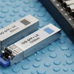
- Datasheets for common optics families often list whether they support RS-FEC or “FEC enabled.” Example module families include Cisco SFP-10G-SR style optics and third-party SR modules such as Finisar FTLX8571D3BCL (model- and platform-specific). Verify with your switch’s optics compatibility matrix before deploying.
- For 10G SR optic examples seen in the field, third-party options like FS.com SFP-10GSR-85 may work, but FEC negotiation and DOM thresholds still depend on the host platform.
Authority notes: IEEE 802.3 governs Ethernet physical-layer behavior; vendor datasheets and switch transceiver guides specify the practical FEC implementation and requirements. [Source: IEEE 802.3 (Ethernet physical layer)] [Source: Cisco SFP/Switch optics documentation] [Source: Finisar and FS.com transceiver datasheets]

Benefits and trade-offs: margin, reach, and latency
The primary engineering benefit of FEC is improved correction capability, which effectively increases link margin. In a tight 5G backhaul or fronthaul route—where connector cleanliness, patch loss, and micro-bends are unavoidable—FEC can be the difference between a stable link and intermittent CRC errors.
The main trade-off is latency and processing overhead. In time-sensitive networks, even small added latency can impact scheduling and jitter budgets. Also, if the link is already too degraded, FEC cannot correct beyond its threshold, and you will see a hard failure mode rather than a graceful degradation.
Pro Tip: If your switch reports “FEC corrected” counters but you still see rising CRC or frame drops, do not assume FEC is “working.” Correction counters can saturate near the FEC threshold; the right move is to measure optical power, check fiber continuity, and verify patch panel loss with an OTDR or at least a calibrated power meter before changing FEC again.
Real-world deployment scenario: 5G fronthaul swap with tight budget
In a 5G fronthaul aggregation site, a carrier deployed a leaf-spine data center edge feeding a regional radio unit pool. The optics were 25G over single-mode fiber (SMF) with a nominal link loss budget of about 2.5 dB margin for connectors, splices, and patching. After a field maintenance window, patch cables were replaced and the link came up but began error bursts during peak traffic.
Engineers pulled transceiver DOM readings and observed that received power sat near the lower comfort range, while the switch showed FEC correction activity increasing over hours. The fix was not “more power” but mode alignment: the line card was configured for an FEC profile that matched the original vendor’s behavior, while the replacement transceiver defaulted differently. Once the host forced the correct FEC mode (or the replacement module was swapped to the compatible family), the link stabilized and the error bursts disappeared.
Selection criteria checklist for choosing or enabling FEC
Use this ordered checklist when planning a transceiver swap, a new line card rollout, or a fiber plant change.
- Distance and loss budget: calculate worst-case dB loss including connectors, splices, patch cords, and aging margin.
- Target BER/CRC behavior: confirm what your switch reports (CRC errors, FEC corrected/uncorrected counters).
- Switch and line card compatibility: validate FEC mode negotiation with the exact host platform and firmware version.
- DOM support: ensure the module exposes correct diagnostics (temperature, bias current, TX power, RX power) and that thresholds do not trigger alarms.
- Operating temperature range: verify transceiver and host airflow; marginal temperature can alter optical output power and receiver sensitivity.
- Operating mode constraints: check whether FEC is configurable, auto-negotiated, or fixed per module family.
- Vendor lock-in risk: third-party optics can work, but FEC behavior may diverge; plan a compatibility test before mass rollout.
- Latency budget: for fronthaul or time-sensitive processing, confirm end-to-end latency impact for your coding and rate.
Common mistakes and troubleshooting tips (FEC-related)
These are frequent failure modes seen during real transceiver commissioning and fiber acceptance testing.
-
Mistake: Enabling FEC on one side but leaving the other side in a different mode (or relying on “auto” when the host expects a fixed profile).
Root cause: FEC framing and decoding parameters mismatch, leading to link instability under load.
Solution: Force the same FEC mode in the host, verify firmware compatibility, then re-test under traffic with error counters monitored. -
Mistake: Assuming FEC guarantees link stability even when RX power is out of range.
Root cause: FEC can correct only within a correction threshold; beyond it, the link exhibits hard failures and rising uncorrectable errors.
Solution: Measure RX power at the patch and at the far end; clean connectors, verify polarity, and check for excessive bend loss or bad splices. -
Mistake: Ignoring connector cleanliness and fiber plant events after a maintenance swap.
Root cause: Increased reflectance or attenuation changes the optical signal-to-noise ratio; FEC counters may initially look “fine” then degrade.
Solution: Inspect with a fiber microscope, re-terminate if needed, validate with OTDR/optical loss tests, and confirm patch cord grade (OM3/OM4 or SMF class). -
Mistake: Treating DOM alerts as benign when FEC correction counters are rising.
Root cause: Temperature or bias drift can reduce optical margin while the link remains “up.”
Solution: Correlate DOM trends with error counters; adjust airflow, replace marginal modules, and validate threshold settings.
Cost and ROI note: when FEC is worth the operational effort
In many deployments, FEC-related configuration changes cost near zero, while the payoff is reduced truck rolls and fewer outage minutes. Typical module pricing varies widely by rate and vendor: OEM optics often cost about 1.2x to 2.0x third-party pricing, but they may reduce compatibility risk and RMA cycles. Over a multi-year TCO horizon, the ROI comes from fewer failed link incidents, better acceptance test pass rates, and improved mean time to repair.
However, do not ignore the “hidden” costs: added latency can affect application performance, and misaligned FEC modes during upgrades can cause downtime. Plan a staged rollout with traffic replay and capture FEC corrected/uncorrected counters to build confidence before scaling.

FAQ: FEC in transceivers for engineers and buyers
What does FEC actually improve on an optical link?
FEC improves the receiver’s ability to correct bit errors, effectively increasing link margin and allowing operation closer to the sensitivity limit. It reduces the probability of CRC/frame drops when the link is degrading due to loss or noise. When degradation exceeds the correction threshold, the link still fails.
Will FEC increase latency enough to matter?
It can. Latency overhead depends on coding choice, symbol rate, and the host forwarding path. For latency-sensitive systems, measure end-to-end latency in your topology rather than relying on generic vendor claims.
Can I mix different vendor transceivers with the same FEC label?
Sometimes yes, but not safely by assumption. Even if both sides “support FEC,” the exact implementation and negotiation details may differ by vendor and firmware. Always validate with your switch’s optics compatibility matrix and test under load.
How do I confirm FEC is enabled and healthy?
Check switch or line card diagnostics for FEC enabled status and counters such as corrected and uncorrected events. Pair this with optical measurements from DOM or a power meter to ensure the link is not simply “barely surviving.”
What are the first checks when errors rise after an optics swap?
First, verify FEC mode alignment and firmware compatibility, then measure TX/RX power and confirm connector cleanliness and polarity. Next, inspect for patch cord grade mismatch or excessive bend loss, and use OTDR or loss testers if needed.
Does FEC replace proper fiber maintenance?
No. FEC is a resilience tool, not a substitute for clean connectors, correct polarity, and accurate loss budgeting. If the plant is out of spec, FEC will eventually hit its correction limit.
If you are planning a transceiver refresh or a 5G fronthaul/backhaul migration, start by validating FEC mode compatibility and optical margin using your host diagnostics, then lock in the build with a controlled fiber acceptance test. Next step: review link budget and DOM diagnostics to prevent “it came up but it fails later” scenarios.
Author bio: Telecom engineer with hands-on experience commissioning 5G fronthaul and data center optics, including DWDM transport and PON access troubleshooting. Previously deployed field test procedures for FEC mode alignment, DOM threshold validation, and optical budget acceptance.