PROFINET over fiber is often the difference between stable motion control and unpredictable downtime in noisy industrial environments. This quick reference helps plant engineers and integrators select and deploy a factory fiber transceiver that matches PROFINET requirements, switch behavior, and real link budgets. You will get practical selection criteria, deployment math you can reuse on the floor, and field troubleshooting patterns from common failure modes.
Where PROFINET fiber transceivers fail in real plants
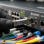
In factory networks, the transceiver is not just a physical connector; it is an optical and electrical compatibility contract between your industrial switch, your fiber plant, and your maintenance process. PROFINET deployments commonly use managed Ethernet switches with redundancy (often ring topologies) and strict timing budgets for cyclic traffic. A mismatched transceiver class, insufficient optical budget, or temperature drift can cause intermittent link flaps that look like “software issues” but are actually optical margin loss.
Before you buy, capture the real constraints: link distance, fiber type (single-mode vs multimode), connector (LC is typical), optical interface standard (SFP/SFP+/SFP28/QSFP), and the operating temperature at the cabinet location. Then confirm the industrial switch’s transceiver compatibility list and DOM support expectations for monitoring.
PROFINET-compatible transceiver types and key specs
Most PROFINET fiber links in industrial cabinets are built using SFP or SFP-based optics (depending on switch port speed). The selection hinges on wavelength, reach, and optical power levels that must fit your measured link loss plus a margin. For reference, below are common modules used in factory networks.

| Form factor | Typical data rate | Wavelength | Typical reach | Connector | Typical optical type | Power / monitoring | Operating temperature |
|---|---|---|---|---|---|---|---|
| SFP (industrial) | 1G | 1310 nm | Up to 10 km (SM) | LC | Single-mode | Low power; SFF-8472 DOM via I2C | -40 to +85 C (varies by vendor) |
| SFP+ | 10G | 850 nm | Up to 300 m (MM, OM3/OM4) | LC | Multimode | DOM; typically higher power than 1G | -40 to +85 C (varies) |
| SFP28 | 25G | 1310 nm | Up to 10 km (SM) | LC | Single-mode | DOM; tighter optical budgets | -25 to +70 C or -40 to +85 C |
Standards and references: verify electrical and optical behavior against the relevant SFF specifications and Ethernet PHY expectations. For transceiver electrical and DOM interfaces, the SFF-8472 digital diagnostic standard is widely referenced in vendor datasheets. For Ethernet link behavior and optics interaction, align with IEEE 802.3 PHY requirements. [Source: IEEE 802.3][Source: SFF-8472 Digital Diagnostic Monitoring]
Concrete PROFINET link mapping: distance, fiber type, and budget
In practice, you should compute optical margin using measured fiber loss (splice + connector + cable attenuation) and then compare it to the module’s published receive sensitivity and minimum transmit power. For example, with a 10G 850 nm MM plan, if your OM4 link loss measured in the field is 2.8 dB, plus 0.5 dB per mated connector set and 3 splice events, your total loss may land around 4.5 to 6 dB depending on distance and splices. You then ensure your transceiver supports that budget with vendor margin for aging and temperature.
On SM links, the same logic applies but attenuation is lower; the risk shifts to connector cleanliness and end-face damage, which can be worse than you expect after repeated maintenance. Use an optical power meter and a proper fiber inspection scope; do not rely on “as-built” drawings alone.
Comparison: factory fiber transceiver options for industrial switches
Industrial buyers usually face two constraints at once: the switch requires a particular transceiver compatibility profile, and the factory demands environmental durability. The table below compares common vendor strategies and what they mean for PROFINET stability and maintenance.

| Option | Typical module examples | Compatibility risk | Monitoring | Optical margin behavior | Best fit in PROFINET plants |
|---|---|---|---|---|---|
| OEM or switch-vendor SFP/SFP+ optics | Cisco SFP-10G-SR; Cisco-compatible optics | Low (best match to firmware) | Often full DOM support | Vendor-published budgets align closely | Critical lines with strict change control |
| High-quality third-party with documented compatibility | Finisar FTLX8571D3BCL; FS.com SFP-10GSR-85 (examples) | Medium (verify switch list) | DOM usually supported; confirm thresholds | Can be stable, but verify min/max optical power | Cost-sensitive plants with tested spares |
| Unverified “compatible” optics | Generic listings without DOM specs | High (link flaps, speed fallback) | May be partial or non-standard | Margin can be worse under temperature | Not recommended for PROFINET control traffic |
Why DOM matters for PROFINET maintenance
Many industrial switches expose alarms for transceiver parameters such as laser bias current, received optical power, and temperature. For PROFINET, you are not just trying to “get link up”; you want early warning before cyclic traffic degrades. If DOM thresholds are wrong or not supported, you lose predictive maintenance signals and end up reacting to outages.
Use the switch’s diagnostics to confirm DOM fields are readable immediately after install. If the switch shows “transceiver type unknown,” keep the spare on a staging port to validate before deploying to active PROFINET rings.
Pro Tip: In industrial ring redundancy, transceiver link flaps can trigger protection switching repeatedly. Even if PROFINET recovers, the resulting micro-outages can increase controller retransmissions and raise CPU utilization. Track DOM “RX power low” events and correlate them with switch port logs; optics aging often shows up as a slow downward trend long before total failures.
Selection criteria checklist for a factory fiber transceiver
Use this ordered decision list. If you can answer each item with evidence, you will avoid most real-world failures.
- Distance and fiber type: single-mode vs multimode; measure end-to-end loss with an OTDR or certified power test.
- Required data rate and port type: match SFP vs SFP+ vs SFP28 to the switch’s port speed; do not assume down-negotiation will occur.
- Wavelength and optics standard: 850 nm MM, 1310 nm SM, or other vendor-specific variants; confirm reach for your exact fiber grade (OM3 vs OM4).
- Switch compatibility and firmware behavior: check the switch vendor’s tested optics list; validate with one “canary” port before scaling.
- DOM support and threshold mapping: ensure the switch can read SFF-8472-style diagnostics and that alarms are meaningful, not silent.
- Operating temperature: verify the module rating matches cabinet airflow and measured ambient temperature; include a safety margin for heat soak.
- Connector and cleaning plan: confirm LC type, ferrule cleanliness requirements, and whether you can implement a repeatable cleaning workflow.
- Vendor lock-in risk and spares strategy: price spares as a TCO item; stock a small verified set for each switch family and optics class.
Real-world deployment scenario: 10G PROFINET fiber in a leaf-spine factory
Consider a 3-tier factory network where 48-port ToR industrial switches connect to a leaf aggregation pair, and then to two core switches. Each ToR serves machine cells using PROFINET cyclic traffic at 10G uplinks. The plant uses 10G 850 nm over OM4 for runs averaging 180 m, with measured link loss of 5 to 7 dB including connectors and splices. Engineers deploy a mix of OEM optics for the uplinks on the ring-protection switches and third-party verified optics for non-redundant spurs, cutting optics cost while maintaining stable DOM alarms.
In this scenario, they also keep two spare optics per switch model and optics class, because the cost of a half-day downtime event typically dwarfs the delta between OEM and third-party. After install, they monitor port error counters and DOM thresholds for the first 30 days to confirm stability before removing staging spares.
Common pitfalls and troubleshooting for factory fiber transceivers
Below are failure modes you will see in industrial PROFINET environments. Each includes a root cause and a practical fix.
-
Pitfall 1: Link flaps only under temperature rise
Root cause: module operating beyond its rated temperature or insufficient airflow; laser bias drift reduces effective optical power.
Solution: measure cabinet ambient with a data logger, enforce airflow, and replace with a module rated for the measured range. Validate DOM temperature and bias current trends. -
Pitfall 2: “Link up” but PROFINET traffic becomes unreliable
Root cause: marginal optical budget causes intermittent CRC errors even when link remains up; cyclic traffic exposes packet loss quickly.
Solution: pull interface error counters, check for rising CRC/FCS errors, and re-test optical power. Clean connectors and verify polarity/patching, then confirm module receive sensitivity margin. -
Pitfall 3: Works on one switch, fails on another
Root cause: transceiver compatibility quirks with specific firmware, DOM interpretation differences, or speed negotiation limitations.
Solution: validate optics on the exact switch model and firmware revision. Use staging ports, and if needed, standardize optics by switch family to reduce variability. -
Pitfall 4: Persistent downshift or no link after maintenance
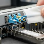
Root cause: connector contamination or damaged ferrules; even a small end-face scratch can add several dB of loss.
Solution: inspect with an end-face scope, clean with an approved process, and replace patch cords if inspection shows damage. Re-measure link loss after each intervention.
Cost and ROI note: what you actually pay for
Typical pricing for a factory fiber transceiver varies by speed, reach, and temperature grade. As a rough planning range, 1G SFP optics often land in the tens of dollars, while 10G SFP+ multimode modules can be higher, and 25G SFP28 single-mode optics usually command the highest per-port cost. OEM optics may cost 20% to 60% more than third-party modules, but the ROI comes from reduced troubleshooting time and fewer “unknown compatibility” incidents.
TCO should include: (1) change-control overhead, (2) downtime risk for PROFINET control loops, (3) spares stocking, and (4) the labor cost of optical cleaning and re-testing. In many plants, buying verified third-party optics with documented compatibility and strong DOM support is the best balance, as long as you run a canary validation on the exact switch and firmware before scaling.

FAQ: factory fiber transceiver for PROFINET fiber links
What does a factory fiber transceiver need to support for PROFINET?
It must match the switch port speed and fiber type, and it must fit the optical budget for your measured link loss. For operations, DOM support and readable diagnostics help you monitor RX power and temperature trends before failures impact PROFINET cyclic traffic.
Can I use third-party optics instead of OEM?
Yes, but only after validating compatibility with your exact industrial switch model and firmware revision. Run a staged test on a non-critical port, confirm stable link behavior, and verify DOM alarm readability before deploying across a PROFINET ring.
How do I choose between multimode and single-mode for factory runs?
If your distances are within the published OM4 reach for your selected data rate and wavelength, multimode can be cost-effective and simpler. For longer runs or future-proofing, single-mode usually offers more reach and less modal sensitivity, but requires careful connector cleanliness and inspection.
What optical measurements should I record during commissioning?
Record end-to-end loss (OTDR or certified power testing), connector counts and splice counts, and initial DOM readings for RX power and temperature. Store these values per link so you can compare after maintenance events or suspected degradation.
Why do I see link up but PROFINET still degrades?
Mismatched optical margin can produce rising CRC or FCS errors that do not always immediately drop the link. Clean connectors, re-check polarity and patching, and verify that the module’s receive sensitivity and transmit power meet your budget with margin.
Are industrial temperature-rated transceivers always required?
They are strongly recommended when cabinets run hot or airflow is inconsistent. If you can document ambient temperature and airflow conditions and they remain within the module’s rated range, you may choose standard-grade optics, but industrial environments frequently exceed assumptions.
Choosing the right factory fiber transceiver for PROFINET is a disciplined process: match the exact optics class to your switch and fiber plant, validate DOM behavior, and budget optical margin using measured loss. Next step: review your switch’s compatibility list and run a canary deployment plan using the checklist above via PROFINET fiber network design.
Author bio: I design and deploy fiber-based industrial Ethernet links, including transceiver qualification, optical budget verification, and field commissioning workflows. I specialize in turning compatibility constraints and ROI math into reliable rollout plans for PROFINET and similar real-time systems.