When your leaf-spine fabric is running at 400G but your workload mix is shifting toward AI training bursts, the next bottleneck is often optics, not switching silicon. This article helps network engineers and data center operators plan enterprise optics for a staged 800G rollout that preserves compatibility, minimizes downtime, and avoids “mystery” link instability. You will get selection criteria, a specs comparison table, and field-tested troubleshooting patterns based on IEEE Ethernet PHY expectations and vendor datasheets.

How the 800G shift changes enterprise optics decisions
Moving from 400G to 800G is not just a “double the speed” upgrade; it changes how transceivers map to lanes, how forward error correction (FEC) behaves, and how optics budgets are managed end to end. Most modern 800G implementations align with Ethernet line-rate framing and commonly use parallel optics architectures (for example, 8x lanes at higher per-lane rates with aggregate signaling). In practice, engineers must confirm that the switch port optics profile matches the transceiver coding and that the fiber plant can support the required reach with a stable optical power budget.
From an operations standpoint, the biggest risk is a staged rollout where some spines or leaves still run 400G while others move to 800G. That scenario forces you to think about transceiver interoperability, DOM telemetry thresholds, and consistent patching practices. If you reuse existing trunks, you also need to verify whether the link budget assumed by the vendor matches your actual connector cleanliness and patch-cord aging.
What IEEE and vendor guidance imply for link behavior
Ethernet PHY layers for high-speed links rely on deterministic lane behavior plus FEC. While the exact FEC mode can vary by implementation, the common operational takeaway is consistent: if optical power levels or signal-to-noise ratio fall outside the transceiver’s specified range, you can see intermittent link flaps even when the link “comes up.” Engineers should treat vendor “link up” as necessary but not sufficient, and they should validate stability under realistic load.
For standards context, see IEEE Ethernet guidance for 400G and 800G PHY evolution as published in the IEEE 802.3 family. Also, treat module compatibility as a vendor-supported question, not a best-effort one. IEEE Standards Portal [Source: IEEE 802.3 family] and vendor PHY and FEC documentation vary by vendor [Source: IEEE and vendor datasheets]
Pick the right 800G optics class: SR8, LR8, and beyond
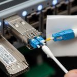
In enterprise optics planning, you typically start with distance and then choose an optics class that matches your fiber type and reach. For 800G, the most common near-data-center options are short-reach multimode based on MPO/MTP cabling, and longer-reach single-mode options for broader campus or inter-rack runs. If you are transitioning inside a data center, SR-class optics usually dominate because they fit the existing OM4/OM5 plant.
However, “SR” is not a single thing. You must match the transceiver form factor and lane count to the switch cage type, and you must confirm that your vendor supports the required modulation and FEC profile. Some switch vendors restrict optics to their supported list, particularly for higher-speed ports.
| Spec | 800G SR (Multimode, typical) | 800G LR (Single-mode, typical) | Example module models to sanity-check |
|---|---|---|---|
| Nominal wavelength | Multi-wavelength parallel (often ~850 nm class) | Single-mode wavelengths (often ~1310 nm class) | Finisar/FS.com SR and LR families vary by generation |
| Connector | MPO or MTP (typically 8-fiber or 12-fiber depending on design) | LC (often 8x parallel via breakout optics) or MPO variant depending on vendor | Check cage labeling: “MPO-xx” vs “LC” |
| Typical reach class | ~100 m on OM4/OM5 (vendor dependent) | ~10 km on single-mode (vendor dependent) | FS.com 800G SR/LR offerings; OEM equivalents |
| Data rate | 800G aggregate | 800G aggregate | Always confirm “800G Ethernet” compatibility |
| Power budget (practical view) | Constrained; connector and patch loss matter a lot | More forgiving; still sensitive to bad splices | Use vendor link budget with your measured insertion loss |
| Operating temperature | Often 0 to 70 C for standard modules; some support extended | Often 0 to 70 C for standard modules; extended variants exist | Always match your cabinet airflow assumptions |
Reality check: exact reach, connector mapping, and temperature ranges must be confirmed in the specific transceiver datasheet and the switch vendor’s compatibility matrix. As examples of how engineers verify optics, you may see legacy 10G optics part numbers like Cisco SFP-10G-SR and Finisar FTLX8571D3BCL, but 800G will use different form factors and lane mapping. Treat those older part numbers as a reminder to read the datasheet, not as direct substitutes.

From 400G to 800G: a staged enterprise optics rollout plan
A practical rollout rarely flips the entire fabric at once. A common staged approach is upgrading one tier (for example, a subset of ToR or a block of spine ports) while keeping the rest on 400G. You then validate telemetry, error counters, and application-level performance before expanding. This reduces blast radius when you discover a transceiver compatibility edge case or a patching mistake.
In a typical migration, you also want a cabling strategy that avoids “silent drift.” For example, if your 400G optics used 12-fiber MPO trunks, but your new 800G optics expects different fiber mapping, you may need polarity rules and strict labeling. If you mix trunks without enforcing polarity, you can get links that appear up but have high error rates under load.
Operational steps engineers actually run
- Inventory current optics: form factor, vendor, serials, DOM thresholds, and the exact switch port speed profile.
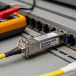
- Measure fiber with a certification tool: insertion loss, reflectance, and end-face inspection results for every trunk you plan to reuse.
- Confirm compatibility using the switch vendor supported optics list for the exact port mode (including any “800G native vs 2x400G breakout” constraints).
- Plan patch labeling for lane mapping and polarity. Use consistent numbering and record patch cord lengths.
- Pilot under load: run traffic at expected utilization (for example, 60 to 80 percent line rate equivalent) and watch link error counters for at least several hours.
Pro Tip: In the field, the most expensive “failed optics” are often not the transceiver itself but a connector cleanliness or patch-cord substitution issue. Even when the link negotiates, a dirty MPO end-face can push your optical power into a margin zone where FEC retries rise only during specific traffic patterns.

Selection checklist: enterprise optics factors that decide success
Engineers usually think they are choosing between “SR or LR.” In practice, the winner is the optics that matches the switch cage, the fiber plant, and your operational tolerance for failure. Use this ordered checklist to reduce late surprises.
- Distance and reach class: match your measured fiber length plus margin to the vendor reach spec for your exact cable type (OM4 vs OM5 vs OS2).
- Switch compatibility: confirm the transceiver is supported for the exact switch model, port type, and speed mode. Vendor lock-in is real at these speeds.
- Connector and polarity: verify MPO/MTP type, fiber count, and polarity requirements. Document polarity mapping before you touch patching.
- DOM support and telemetry: ensure the switch reads DOM (optical receive power, bias current, temperature) and that alarms are within your monitoring thresholds.
- Operating temperature and airflow: check the module temperature range against your cabinet airflow and ambient assumptions.
- Vendor lock-in risk: estimate replacement availability and lead times. If you buy third-party, confirm your switch vendor’s acceptance stance.
- Power and cooling impact: higher-density optics can increase local thermal load; validate airflow paths and cable management.
Common mistakes and troubleshooting patterns during 800G transitions
Below are failure modes that show up repeatedly during enterprise optics upgrades. Each includes root cause and a practical fix you can apply quickly.
“Link up” but high errors under traffic
Root cause: optical budget marginality due to excessive insertion loss, aging patch cords, or incorrect MPO polarity mapping that worsens signal quality only when traffic stresses the link. Solution: re-check MPO polarity, clean both ends, and use a power meter or switch telemetry to confirm RX power is within the vendor recommended operating window. If possible, compare a known-good port and transceiver pair to isolate whether the issue follows the optic or the fiber path.
Intermittent flaps after a successful pilot
Root cause: thermal hotspots or airflow obstruction near the module cage. Some 800G transceivers are sensitive to temperature excursions, and bias current can drift. Solution: verify cabinet airflow with actual sensor readings at the cage area, confirm fan tray settings, and reseat or re-route cables that block intake flow. Then re-run a stability test while monitoring temperature and bias current DOM telemetry.
Incompatibility from mixed optics generations
Root cause: transceiver form factor or firmware expectations mismatch with the switch port optics profile. The port may negotiate partially, or it may behave unpredictably. Solution: enforce homogeneity per port group (same vendor model family and DOM behavior) during the migration window. Only mix when the switch vendor explicitly supports it, and record which transceivers were installed on each port before you start troubleshooting.
Polarity surprises with MPO trunks
Root cause: using a trunk that was certified for a different polarity standard than your new optics expects. Solution: re-certify and re-label patching. Use consistent polarity documentation and physically verify fiber routing at the patch panel before inserting optics. If you see errors that improve after swapping patch cords, suspect polarity before you suspect the transceiver.
Cost and ROI note for enterprise optics at scale
Pricing varies by form factor and vendor, but many enterprises see 800G optics as a meaningful line item. As a rule of thumb for budgeting, SR-class 800G modules can land in the low hundreds to low thousands of dollars per transceiver, while LR-class modules often cost more due to single-mode optics complexity. OEM optics may carry higher unit costs but can reduce operational downtime and RMA friction; third-party optics can lower acquisition spend but may increase time spent on compatibility validation and incident response.
For TCO, include labor hours for certification, cleaning supplies, spare inventory, and the cost of downtime during cutover. A common ROI pattern is that the biggest savings come from preventing “repeat migrations” caused by cabling surprises. If you invest in fiber certification and labeling up front, you reduce the number of truck rolls and swap cycles required later.
FAQ for engineers buying enterprise optics for 800G
What fiber type should I assume for most enterprise 800G deployments?
Inside data centers, many teams start with OM4 or OM5 multimode for short reach, using MPO/MTP trunks. For longer runs, OS2 single-mode with LC or MPO variants is typical. The right answer depends on measured insertion loss and the vendor’s reach budget for your exact transceiver model.
Can I reuse my existing 400G optics fiber trunks for 800G SR?
Often you can reuse the trunks, but you must verify connector cleanliness, insertion loss, and polarity mapping. Also confirm whether the new 800G optics expects different fiber mapping or a different MPO polarity standard. If your certification reports are older than a year, re-certify before you scale.
Do I need to worry about DOM telemetry and monitoring thresholds?
Yes. DOM telemetry is how you detect drift early, especially for bias current and RX optical power. If your monitoring thresholds are too tight or too loose, you may miss early warnings or create noisy alarms that hide real faults.
Is third-party enterprise optics safe for 800G, or should we stick to OEM?
Third-party modules can work well when the switch vendor supports them and the module family is validated for your port mode. The risk is not just link negotiation; it is long-term stability, DOM behavior, and supportability during RMA. For high-value spines, many teams standardize on OEM for the first rollout wave.
What is the fastest way to troubleshoot an 800G link that won’t stabilize?
Start with optics swap and fiber path isolation: compare a known-good port, clean and inspect MPO/LC ends, and verify polarity. Then use DOM telemetry and switch error counters to see whether the issue follows the transceiver or the fiber. Finally, re-check airflow and temperature at the cage after reseating and cable changes.
How should we plan spares to minimize downtime during the transition?
Keep spares that match your exact switch port type and optics class, plus a small pool of known-good patch cords. Track which optics were installed per port so you can swap quickly without guessing. During the first 30 to 60 days, prioritize spares for the highest-utilization links and the most failure-prone cable routes.
If you want the safest path from 400G to 800G, treat enterprise optics as a system: transceiver model, port mode, fiber certification, polarity, and telemetry together. Next, consider a related planning topic like 100G to 400G optics transition lessons to avoid repeating the same operational mistakes at higher densities.
Author bio: I have deployed high-speed Ethernet optics in production data centers, validating fiber certification, DOM telemetry alarms, and cutover runbooks under real traffic loads. I write from hands-on field experience and cite standards and vendor documentation to keep enterprise optics decisions defensible.